
CMOS LFSR Vintage Atari Sound Effects Generator

The circuit design consists of a CMOS Linear Feedback Shift Register (LFSR) that is utilized to generate sound effects reminiscent of vintage Atari games. The LFSR operates by shifting bits through a series of flip-flops, where the output of certain flip-flops is fed back into the input through a series of exclusive OR (XOR) gates. This feedback mechanism creates a pseudo-random binary sequence, which can be manipulated to produce various sound effects.
The schematic typically includes a series of CMOS integrated circuits, which are known for their low power consumption and high noise immunity. Key components include the shift register, which may be implemented using 74HC595 or similar CMOS shift register ICs, and the XOR gates that determine the feedback configuration. The output from the LFSR can be connected to a digital-to-analog converter (DAC) to produce audible sound waves, or it can be fed directly into a speaker driver circuit.
The configuration of the XOR gates is crucial, as it defines the polynomial characteristic of the LFSR, thereby influencing the sequence of bits generated. Common configurations can be found in literature that describe specific tap positions for different lengths of registers (e.g., 4-bit, 8-bit).
Additionally, capacitors and resistors may be included in the circuit to filter the output and shape the sound waveforms, providing a more refined audio output. Power supply considerations are also important, ensuring that the circuit operates within the specified voltage range for the CMOS components.
Overall, this schematic serves as a foundational design for creating sound effects that capture the essence of classic Atari games, making it a valuable resource for hobbyists and engineers interested in retro gaming technology.Schematic for the CMOS Linear Feedback Shift Register Vintage Atari Sound Effects Generator circuit.. 🔗 External reference
Related Circuits
These relatively simple circuits can be used to transmit information across a small distance. The information typically used includes music from a radio, iPod, or CD player; a microphone and amplifier can also be utilized. People frequently transmit information...
The circuit described operates similarly to a previous design but utilizes a laser pointer to activate the relay instead of a push button. An IR photo transistor (model Q1, Radio Shack 276-145A or equivalent) is connected to the set...
The performance of this sensitive ultrasonic receiver is impressive. It allows users to listen to various sources of ultrasonic sounds, including bugs, bats, and engines. The circuit utilizes a piezo tweeter as an ultrasonic microphone, with amplifier stages Q1...
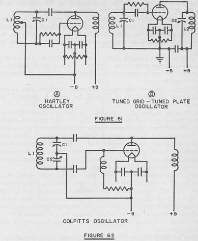
The tuned circuits of capacitance and inductance used in vacuum tube transmitter circuits are often referred to as "tank" circuits, as they serve as reservoirs of RF energy. Blocking capacitors are employed to create a high impedance path for...
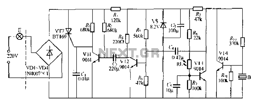
A modified piezoelectric ceramic acoustic-electric transducer is utilized to create a sound and light control system for a stairway walkway with a delay lighting switch. The circuit structure is relatively simple, consisting of diodes VD1 to VD4 and a...
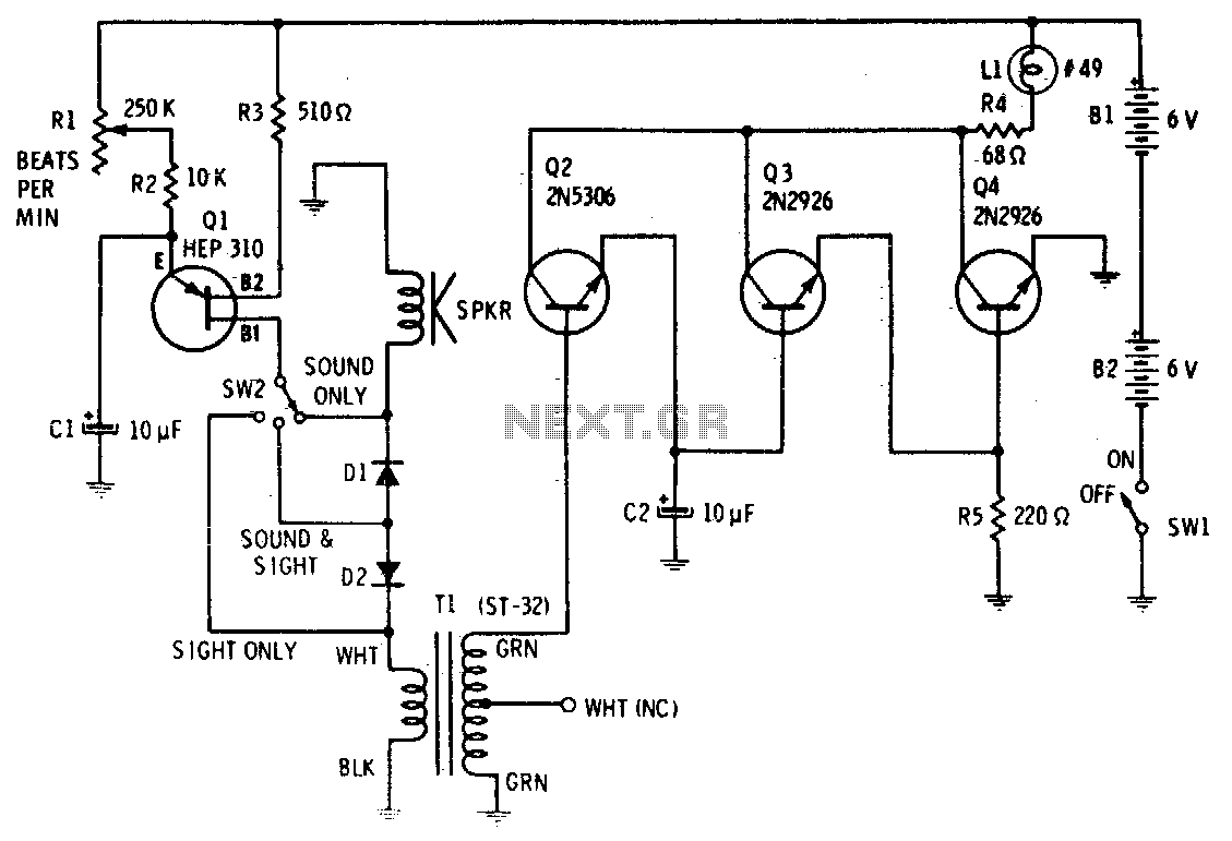
Precise, adjustable control of beats per minute ranges from a slow tempo of 18 to a rapid tempo of 500. These beats are generated acoustically through a speaker, accompanied by a light that flashes in synchronization. When switch SW1...