
Sight n sound metronome

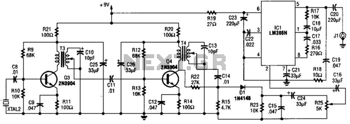
The circuit described operates as a beat generator with adjustable tempo, utilizing a unijunction transistor for pulse generation and a speaker for sound output. The primary component responsible for controlling the beat rate is capacitor C1, which charges through the resistors R1 and R2 when the switch SW1 is engaged. The charging process determines the timing of the pulse output, which can be adjusted to achieve a range of tempos.
Once the voltage across C1 reaches a specific threshold, it activates the unijunction transistor, allowing the stored energy to be discharged into the connected speaker. This discharge creates an audible sound, characterized by a "plop" as the energy is released. The transformer T2 plays a crucial role in shaping the pulse waveform, ensuring that it is suitable for driving the subsequent transistor Q2. This transistor amplifies the pulse signal, providing enough current to actuate the relay LI.
Transistors Q3 and Q4 serve to further amplify the signal, ensuring that the relay is effectively switched on and off in response to the pulse waveform. This switching action can be critical for applications that require precise timing or control, such as in light flashing or other timing-dependent circuits. The inclusion of capacitor C2 is significant as it mitigates the effects of thermal inertia in the lamp, allowing for a more pronounced flash when the relay is activated. This design highlights the interplay between various components to achieve a cohesive and responsive electronic system.Precise, adjustable control of beats per minute from a largo of 18 to a frenzied, high presto of 500, These beats are produced acoustically through a speaker. A light flashes at the same rate. When SW1 is closed, CI begins to charge through Rl and R2. Cl will eventually reach a voltage at which the emitter of unijunction transistor is switched on, "dumping" the energy stored in Cl into an 8 ohm speaker.
To produce a distinct "plop", brief pulses across T2 secondary drive Q2 into conduction The extra gain of Q3 and Q4 are sufficient to briefly switch LI on, then o£f; as the pulse wave pas-ses. Capacitor C2 "stretches" the puise slightly to overcome the thermal inertia of the lamp, so that a bright flash occurs,.
Related Circuits

This circuit utilizes the Mitsubishi M65830 Digital Delay chip, which has proven to be simple and effective for applications requiring a fixed delay. The serial data necessary for achieving various delay settings is not readily available and would significantly...
The 2.25-MHz oscillator Q1 drives amplifier Q2 and XTAL1, an ultrasonic transducer. The transducer is a lead zirconate-titanate type. Taps on T1 and T2 provide low-impedance drive points. The circuit consists of a 2.25-MHz oscillator (Q1) that serves as the...
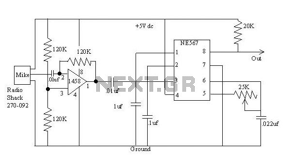
The detector is a bit more complex. It amplifies a microphone and sends the resulting signal to an NE567 tone decoder. The amplifier is half of a 1458 opamp. The two 120K resistors attached to pin 3 keep the...
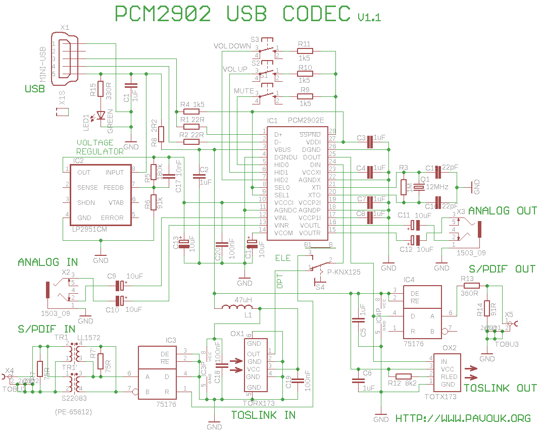
This is a USB sound card featuring the PCM2902 chip. It was designed to test the D/A converters and includes a simple circuit based on the PCM2902. The sound card is equipped with analog input and output, an electrical...
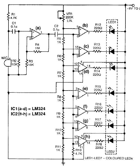
This sound level meter circuit can be used to control the intensity of a sound recording or in a disco. It has 5 measurement domains between 70 and 120 dB. The sound level meter circuit is designed to measure sound...
This project uses an LM3915 bar-graph IC driving two sets of ten LEDs for a 30dB range. The circuit is unique because it has an additional range of 20dB provided by an automatic gain control to allow it to...