
Coil-Less FM Bug

The FM bug circuit described utilizes a basic yet effective design for transmitting audio signals over FM frequencies. The choice of a coaxial cable as an inductor/antenna is particularly advantageous, as it simplifies construction and enhances stability compared to traditional air core inductors. The BF199 transistor is selected for its low capacitance, which is critical in maintaining the integrity of high-frequency signals. The circuit operates at low power, making it suitable for short-range applications, which is typical for FM bug transmitters.
The tuning mechanism is facilitated by a variable capacitor, allowing for frequency adjustments. This component is crucial, as it directly influences the transmitter's ability to lock onto a specific frequency. The use of a trimmer capacitor, while convenient, requires careful handling to ensure accurate tuning without introducing instability. The recommendation to use a ceramic screwdriver is important, as it minimizes the impact of body capacitance during adjustments.
To enhance the audio quality, integrating an audio amplification stage could significantly improve performance. Additionally, substituting the electret microphone with an MP3 player could provide a more consistent audio source, making the circuit more versatile. The layout design of the PCB is essential for minimizing parasitic capacitance, which can adversely affect circuit performance at high frequencies. Careful attention to the arrangement and lead lengths of components is necessary to ensure optimal functionality.
Overall, this FM bug project presents a practical solution for those interested in exploring RF transmission without the complexities often associated with traditional designs. The inclusion of a PCB layout and downloadable resources encourages experimentation and learning within the field of electronics.For months I`ve been looking for a simple FM BUG project, the ones online require inductors which you either have to acquire or build, if you don`t have a LCR meter it becomes rather hard to get the circuit working, specially if you`re a beginner without an oscilloscope! Sometimes they don`t even tell you which inductance is required and you h ave to calculate an estimate, which is the main reason why many high frequency RF projects fail in the first place. From all the projects out there I`ve only seen one which didn`t require an external inductor since it simply used a pcb / trace inductor, however the board was big and the circuit itself had lots of stability issues, etc.
I wasn`t going to waste my time with it. My first FM BUG was based on one of the many schematics out there, it seldom worked. It was microphonic (due to the air core inductor) but the electret capsule itself did not modulate the output at all, needless to say it was very unstable and it never worked properly. This circuit on the other hand performs pretty well, even if you`re manipulating the board or touching the coax it will stay within the tuned frequency (unless you touch the transistor or timing capacitor!).
The power is very low, so don`t expect great distances, specially in populated areas! No surprises there, it`s very similar to other schematics so therefore I won`t go into the working details. Actually I might argue this one is a bit on the low efficiency side, but at the moment I don`t have the equipment to further improve it`s design.
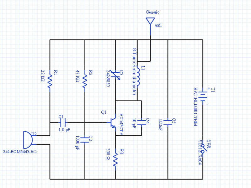
But let`s not focus on that and instead let`s talk about the inductor / antenna, it`s based on a 12cm long 50-75Ohms coaxial cable with one of it`s ends soldered (mesh and core are joined together) this is a big plus, we don`t have to use a flimsy air core inductor and we don`t need a lengthy wire antenna either Great! This tiny ghetto transmitter is guaranteed to work first time, as long as you double check all connections and you make sure your transistor is properly placed and in working order.
I used the BF199 because it`s got a low capacitance and it`s ideal for this type of application, but you may use a 2n2222 or similar general purpose NPN BJT. I know, the schematic calls for a BF259 which is what I used in my simulation, but believe me it works beautifully with the BF199.
I didn`t have a 8. 2pF capacitor so I used a smaller one, which naturally led the transmitter to work on the upper FM broadcast band, but hey ” better than nothing! The sound quality is not the best, this FM Bug could clearly benefit from an audio amplification stage.
Another idea would be to scrap the electret and use an mp3 player instead. I reckon R4 could be ignored in that case but you might want to use a resistor in series with the input capacitor. Another important component is the variable capacitor which forms the tuning circuit, I used a 4. 5-20pF trimmer type capacitor, it`s the first one I found in the junk box, it was a bit flimsy and it required lots of patience to tune but I eventually got it to the point I wanted.
I recommend you get a ceramic screwdriver for the tuning or you can improvise one with a piece of plastic, it`s important because otherwise your body capacitance will affect the transmitter! For those interested I also included the PCB layout, it`s very easy to etch your own PCBs so you shoulddefinitelygive it a try!
Remember to keep the component leads to a minimum, we`re working with high frequencies, any parasitic capacitance, etc. will modify thebehaviourof the circuit one way or another! Click here to download all pertinent files for this project: fmbug_docs. The exports are not in perfect quality due to the PDF printer driver I used, but hey at least I`m providing the PCB layout, other projects leave this as an exercise for the reader (that`s because they never actually built the damn thing!) One improvement over the current layout would be t
🔗 External reference
Related Circuits
This fairly simple circuit makes it possible to place such a wall as a conduit to locate. It is a conduit for power, no water or gas-seeker. The only requirement is that there is tension on the line. The...
At this stage, a whistle is directed into the receiver, and the Infinity Bug will activate. The high-gain amplifier within the Infinity Bug captures audio from its location. It can only be assembled on the provided PC board since...
The Circuit shown can transmit voice to exceptionally good range. Tune trimmer to hear the signal to your near radio. Frequency range is 88-108 MHz. Max current consumption is 30mA. You can power the bug with a 9Volt Battery,...

Power circuit, reset circuit, USB connection, ABDAC sound DAC, interface, JTAG and Nexus debug ports, clocks, and crystal oscillators. Introduction: A good hardware design originates from a proper schematic. Since UC3B devices have a considerable number of pins and...
Here is a simple transmitter that when connected to a phone line, will transmit anything on that line (except the dial tone) to any FM radio. The frequency can be tuned from 88 to about 94 MHz and the...
The schematic below illustrates a simple circuit that is straightforward to construct. One aspect that is not clearly represented in the schematic is the location of certain components. This circuit design comprises a basic arrangement of electronic components, typically including...