
Wireless Bug detector

More: The circuit is based on the 4069UBE. The entire circuit is to feed a 9 volt battery. R1 = 10 MΩ R2 = 4.7 kΩ R3 = 470 Ω R4 = 470 kΩ R5 = 220 kΩ R6 = 1.8 kΩ R7 = 47 kΩ potentiometer T1 = BC548 D1 = LED 5mm Red D2 = LED 5mm Green D3 = 1N4148 C1 = 100 nF C2 = 470 pF IC1 = CD4069UBE Buzzer Switch
The described circuit is a simple power conduit detector utilizing the CD4069UBE IC, which is a hex inverter. The circuit operates on a 9V battery, providing a stable power supply for its components. The main function of this circuit is to detect the presence of a conductive pathway, indicated by the activation of a buzzer and two LEDs (one red and one green).
The circuit includes various resistors (R1 to R7) that serve different roles in biasing, signal conditioning, and adjusting the sensitivity of the detection mechanism. R1, with a value of 10 MΩ, acts as a high-value pull-up resistor, ensuring that the input of the inverter remains high when no signal is present. R2 (4.7 kΩ) and R3 (470 Ω) are used for signal attenuation and conditioning, while R4 (470 kΩ) and R5 (220 kΩ) provide additional biasing to the inverter inputs.
R6 (1.8 kΩ) is likely used in conjunction with the buzzer to limit the current flowing through it, protecting it from damage while ensuring audible feedback is provided when the circuit is activated. The potentiometer R7 (47 kΩ) allows for fine-tuning of the circuit's sensitivity, enabling the user to adjust the threshold at which the buzzer and LEDs activate based on the detected signal.
Transistor T1 (BC548) is utilized as an amplifier or switch within the circuit, allowing for the control of the buzzer and LEDs based on the output from the inverter. The inclusion of diodes D1 (5mm Red LED) and D2 (5mm Green LED) provides visual indicators of the circuit's status, with the red LED likely indicating an active state and the green LED indicating a standby or inactive state.
Capacitors C1 (100 nF) and C2 (470 pF) are used for decoupling and filtering purposes, stabilizing the power supply and preventing noise from affecting the circuit's performance. Diode D3 (1N4148) serves as a protection component, ensuring that current does not flow in the reverse direction, which could damage sensitive components.
The circuit also includes a switch to enable or disable the entire system, allowing for manual control over its operation. The simplicity of this design makes it suitable for various applications where a basic power conduit detection mechanism is required.This fairly simple circuit makes it possible to place such a wall as a conduit to locate. It is a conduit for power, no water or gas-seeker. The only requirement is that there is tension on the line. The antenna in the table can consist of a simple piece of copper wire. The correct adjustment is done through R7, in order to prevent the buzzer and LEDs still light up even though there is no leadership in the area. The circuit is based on the 4069UBE. The entire circuit is to feed a 9 volt battery. R1 = 10 M? R2 = 4.7 kOhm R3 = 470 ? R4 = 470 kOhm R5 = 220 kOhm R6 = 1.8 kOhm R7 = 47 kOhm potentiometer T1 = BC548 D1 = LED 5mm Red D2 = LED 5mm Green D3 = 1N4148 C1 = 100 nF C2 = 470 pF IC1 = CD4069UBE Buzzer Switch 🔗 External reference
Related Circuits
A DTMF-based infrared (IR) transmitter and receiver pair can be utilized to create a proximity detector. This circuit enables the detection of any object capable of reflecting the IR beam and moving in front of the IR LED and...
The first sensor that a robot is typically equipped with is an obstacle detector. It can take three different forms, depending on the type of obstacle to be detected. Obstacle detectors are essential components in robotic systems, designed to enhance...
Is there a way to automatically turn on an LED when it gets dark? A version was created using a relay and photoresistor that functioned properly, but concerns arose regarding potential battery drain. The project aims to integrate with...
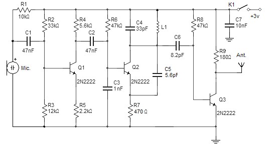
This wireless FM microphone is easy to construct and offers a useful transmitting range of over 300 meters in open air. Despite its minimal component count and a 3V operating voltage, it can effectively penetrate three floors of an...
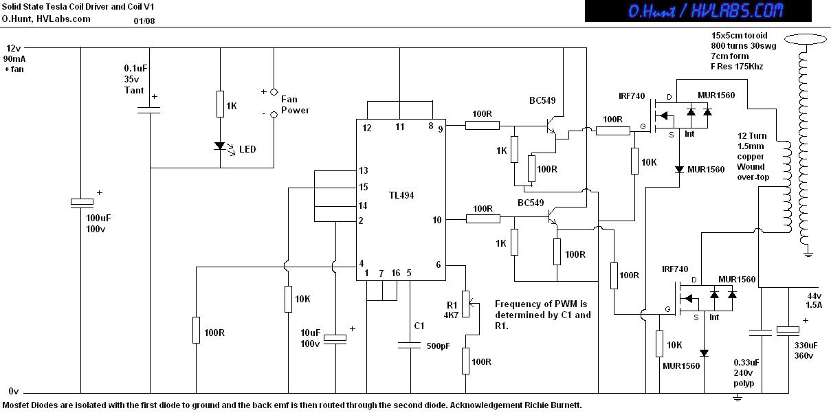
This is a solid-state version of a Tesla coil, replacing the spark gap with MOSFET transistors and utilizing a close-coupled primary coil without capacitors. The method of driving the primary coil varies among designs. After researching various works online,...
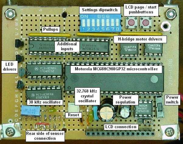
Bugdozer is an autonomous mini-Sumo robot. Her main board consists of a MC68HC908GP32 microcontroller along with input/output support chips, a voltage regulator, a crystal oscillator, and the usual assortment of resistors, capacitors, and switches. All chips are socket mounted....