
Coil-less FM Transmitter

The described circuit comprises a radio frequency (RF) oscillator that utilizes an inverter (N2) in conjunction with a 10.7 MHz ceramic filter, which is a common frequency used in FM broadcasting. This oscillator generates a square wave signal that can be efficiently amplified and transmitted. The output from the inverter is connected to a parallel arrangement of additional inverters (N4 to N6) through another inverter (N3). This configuration ensures that the overall output impedance is low, allowing for direct coupling to an aerial designed for a quarter-wavelength transmission.
The square wave output from the inverters inherently contains multiple harmonics, which is a characteristic of non-sinusoidal waveforms. Specifically, the 9th harmonic of the fundamental frequency (10.7 MHz) is calculated to be 96.3 MHz, which aligns with the center frequency of the FM band, making this circuit suitable for FM transmission applications.
Additionally, a separate stage in the circuit involves an audio amplifier (N1), which processes audio signals captured from a microphone. The amplified audio signal is then fed into a variable capacitance diode (varycap). The varying audio signal modulates the capacitance of the diode, which can be utilized for frequency modulation of the RF signal generated by the oscillator. This modulation is crucial for encoding the audio information onto the RF carrier wave, enabling effective transmission over the designated frequency band.
Overall, this circuit design highlights an efficient method for generating and modulating RF signals for FM transmission, incorporating essential components such as inverters, a ceramic filter, and variable capacitance diodes to achieve the desired performance characteristics.The RF oscillator using the inverter N2 and 10.7Mhz ceramic filter is driving the parallel combination of N4 to N6 through N3.Since these inverters are in parallel the output impedance will be low so that it can directly drive an aerial of 1/4th wavelength. Since the output of N4-N6 is square wave there will be a lot of harmonics in it. The 9th harmonics of 10.7Mhz (96.3Mhz) will hence be at the center of the FM band. N1 is working as an audio amplifier. The audio signals from the microphone are amplified and fed to the varycap diode. The signal varies the capacitance of the varycap and 🔗 External reference
Related Circuits
The FM302E-I-type FM transmitter exciter is utilized in Japan's NEC HPB a 1210 motherboard. It features direct carrier frequency modulation, phase-locked frequency stabilization, and frequency synthesis. The preamplifier (BLF-177 FET) is directly driven by an actuator, achieving a maximum...
This FM spy transmitter can function as a bug transmitter or a DIY FM bug. It utilizes a single IC 74F13, one coil, a capacitor, and one additional component. The FM spy transmitter is a compact device designed for covert...
I have had requests to add a VHF FM transmitter, to the QRP collection. This project is a simple transmitter using only one crystal and will cover 145.00 to 146.00 MHz. The crystal is a 44.9333 MHz crystal for...
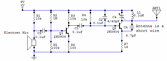
This circuit uses a small microphone to capture the sound and some transistors to generate radio waves that can be picked up by a FM receiver like a car stereo. The first part is the microphone and some resistors...
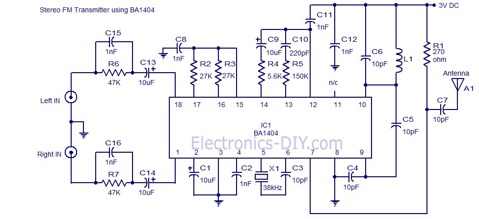
A high-quality stereo FM transmitter circuit is presented. This circuit utilizes the BA1404 integrated circuit from ROHM Semiconductors. The BA1404 is a monolithic FM stereo modulator that includes a built-in stereo modulator, FM modulator, and RF amplifier. The FM...
This compact circuit transmitter processes audio signals from a table or microphone, as well as video signals from a camera, DVD, or video cassette. It can transmit these signals directly from a computer over a free VHF channel. The...