
Stereo FM Transmitter with BA1404

The high-quality stereo FM transmitter circuit based on the BA1404 IC is designed to provide efficient transmission of audio signals with minimal distortion and optimal stereo separation. The BA1404 integrates multiple functionalities, which simplifies the overall design while ensuring robust performance. The operating frequency range of 76 to 108 MHz is suitable for standard FM broadcasting, making this circuit applicable for various audio transmission projects.
The pre-emphasis network, composed of resistors (R6, R7) and capacitors (C13, C14, C15, C16), is crucial for enhancing the signal-to-noise ratio during transmission. By boosting higher frequencies, this network compensates for the inherent limitations of FM receivers, which typically exhibit reduced sensitivity to high-frequency audio components. This careful tuning ensures that the transmitted audio maintains clarity and fidelity when received.
The oscillator circuit, formed by inductor L1 and capacitor C5, determines the carrier frequency of the FM signal. The precise selection of these components is essential, as it directly influences the stability and quality of the transmitted signal. The inclusion of the 38 kHz crystal (X1) provides a stable reference frequency, which is fundamental for generating a consistent composite stereo signal. This reference frequency is pivotal for ensuring that the stereo modulator operates effectively, allowing for accurate transmission of stereo audio signals.
The additional network comprising capacitors (C9, C10) and resistors (R4, R5) plays a significant role in improving channel separation, which is vital for maintaining the integrity of the left and right audio channels. This enhancement minimizes crosstalk between channels, ensuring that the listener experiences a clear and distinct stereo soundstage.
Overall, this stereo FM transmitter circuit exemplifies a well-engineered solution for audio transmission, combining advanced modulation techniques with careful component selection to achieve high-quality performance in FM broadcasting applications.A high quality stereo FM transmitter circuit is shown here. The circuit is based on the IC BA1404 from ROHM Semiconductors. BA1404 is a monolithic FM stereo modulator that has built in stereo modulator, FM modulator and RF amplifier. The FM modulator can be operated from 76 to 108MHz and power supply for the circuit can be anything between 1.25 to 3 volts.
In the circuit R7, C16, C14 and R6, C15, C13 forms the pre-emphasis network for the right and left channels respectively. This is done for matching the frequency response of the FM transmitter with the FM receiver. Inductor L1 and capacitor C5 is used to set the oscillator frequency. Network C9,C10, R4,R5 improves the channel separation. 38kHz crystal X1 is connected between pins 5 and 6 of the IC. Composite stereo signal is created by the stereo modulator circuit using the 38kHz quartz controlled frequency
🔗 External reference
Related Circuits
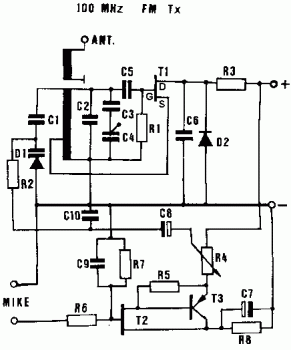
The frequency range is 100-108 MHz. The circuit is a mono circuit that accepts audio input from either a microphone or another source. The input impedance is 1 MΩ, with an input sensitivity of 5 mV and a maximum...
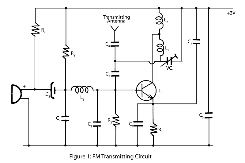
A simple and powerful FM transmitter is an interesting project that utilizes one transistor and operates within a frequency range of 100 MHz. The circuit diagram includes a description of the FM transmitter and various related interesting projects. The FM...
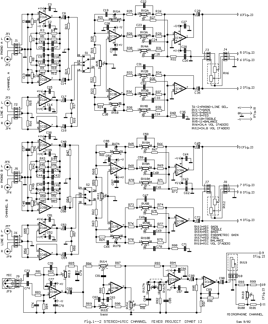
A lot of friends asked me to draw a more shrunk circuit 2-ch mixer, which will contain also, operation CROSSFADER. The circuits can be modified and added also other channels, repeating basic that I give. It can be added...
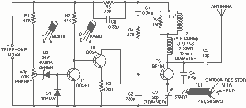
Here is a simple yet very useful circuit which can be used to eavesdrop on a telephone conversation. The circuit can also be used as a wireless telephone amplifier. One important feature of this circuit is that the circuit...

As the number of stations increased and the power levels also rose, receiver performance had to be enhanced. The pentagrid converter, such as the 6BE6 tube (British EK90 valve), was introduced, which was optimized for mixer performance. This included...
Transistors VT1, VT2, and associated RC components are configured to form a multivibrator. The multivibrator operates with resistors Ra and R4 serving as base bias resistors for VT2 and VT1, respectively. When the switch SA is closed after applying...