
Coilless FM transmitter circuit

The described RF oscillator circuit utilizes an inverter (N2) in conjunction with a 10.7 MHz ceramic filter to generate a stable RF signal. The output from this oscillator is routed to a series of inverters (N4 to N6) connected in parallel through another inverter (N3). This configuration is advantageous as it lowers the output impedance, allowing for efficient driving of an aerial antenna that is designed to be 1/4th the wavelength of the operating frequency.
Given that the output from the inverters N4 to N6 is a square wave, it inherently contains multiple harmonic frequencies. Notably, the 9th harmonic of the fundamental frequency (10.7 MHz) is calculated to be 96.3 MHz, which coincides with the center frequency of the FM broadcasting band. This harmonic generation is a critical aspect of the circuit, as it enables the transmission of frequency-modulated signals within the designated FM band.
Additionally, the circuit includes an audio amplifier (N1) that processes audio signals from a microphone. The amplified audio signals are directed to a varicap (variable capacitance) diode. The functionality of the varicap diode is essential, as it allows for dynamic alteration of its capacitance in response to the audio signal levels. This change in capacitance modulates the frequency of the oscillator, effectively producing frequency modulation (FM) of the transmitted signal. The integration of these components facilitates the generation of an RF signal that is modulated with audio information, suitable for radio transmission applications.The RF oscillator using the inverter N2 and 10.7Mhz ceramic filter is driving the parallel combination of N4 to N6 through N3.Since these inverters are in parallel the output impedance will be low so that it can directly drive an aerial of 1/4th wavelength. Since the output of N4-N6 is square wave there will be a lot of harmonics in it. The 9th harmonics of 10.7Mhz (96.3Mhz) will hence be at the center of the FM band . N1 is working as an audio amplifier. The audio signals from the microphone are amplified and fed to the varycap diode. The signal varies the capacitance of the varycap and hence varies the oscillator frequency which produce Frequency Modulation. 🔗 External reference
Related Circuits
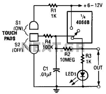
This touch-on switch can be activated through electrical means and can only be reset using a mechanical switch. When the touch terminal is activated by a finger, the SCR turns on and illuminates LED1. The circuit utilizes a silicon-controlled rectifier...
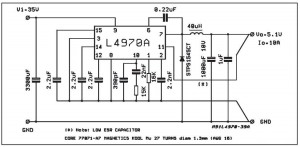
A small-sized and easy-to-build 5V 10A power supply circuit is being sought. This circuit utilizes the L4970A integrated circuit as a 10A switching regulator. It is essential that the power supply input can handle a current of 10A to...
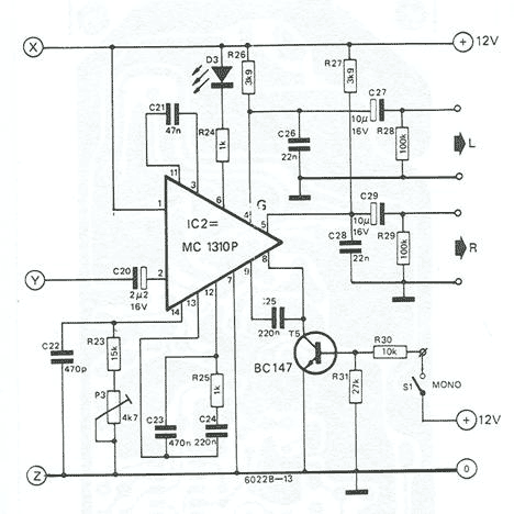
Based on Valvo FD-1A module, TBA120, and MC1310. Operation of the receiver is based on the phase locked loop principle. The FD-1A contains an RF amplifier, oscillator and mixer (made with BF324, BF451 and BF324 transistors, respectively). Tuning is...

This circuit utilizes two operational amplifiers (op-amps) to create a unique sound effect. The first op-amp, CA741, is configured as a standard astable multivibrator, generating timing pulses controlled by components C1, R2, and variable resistor VR1. The output from...
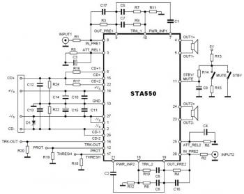
This is a stereo amplifier circuit diagram. The amplifier will produce stereo output channels with a power audio output that can reach up to 70W for each channel. The amplifier is built using the STA550 chip from STMicroelectronics. It...
The Arduino Uno features an ATMEGA328P-PU microcontroller and various additional components on the board. The objective is to program the microcontroller without relying on the Arduino software, utilizing only the essential components. The goal is to develop projects independently...