
Color Organ Light

The described circuit appears to function as an automatic gain control (AGC) system, which is crucial in various audio and signal processing applications. The AGC circuit is designed to maintain a consistent output level despite variations in the input signal amplitude. This is particularly useful in environments where the input signal may fluctuate widely, such as in audio recording or communication systems.
The circuit likely employs a feedback mechanism that monitors the output level and adjusts the gain accordingly. Key components in such a circuit typically include operational amplifiers (op-amps), resistors, capacitors, and possibly a diode for rectification. The op-amp can be configured in a non-inverting or inverting configuration depending on the desired output characteristics.
In operation, when the input signal is low or absent, the circuit will automatically increase the gain to ensure that the output remains at a usable level. Conversely, if the input signal is strong, the gain will be reduced to prevent distortion and clipping. This dynamic adjustment allows the circuit to "fire" or activate even in silence, as it can detect minute changes in the input signal.
The design may also incorporate a time constant, determined by the RC (resistor-capacitor) network, which influences how quickly the circuit responds to changes in input level. A longer time constant will yield smoother gain adjustments, while a shorter time constant will allow for faster response times, which can be beneficial in certain applications.
Overall, this AGC circuit is essential for ensuring optimal performance in systems where signal integrity and consistent output levels are critical.This circuit works REALLY well. Notice how it will fire even in complete silence. This provides a sort of automatic gain control. 🔗 External reference
Related Circuits
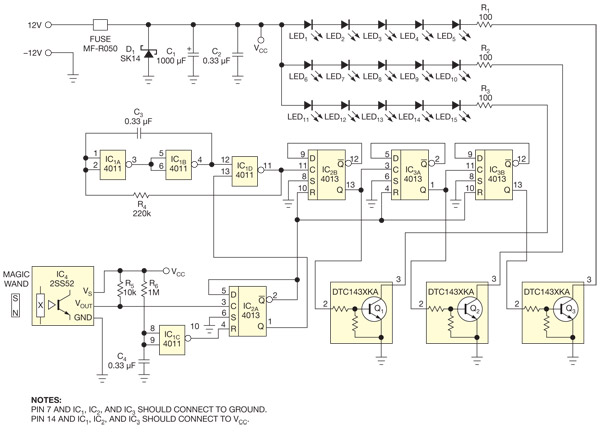
This circuit enables the activation of holiday bulbs with a wave of a magic wand. The strings of lights flash in a sequential manner. The core concept relies on a magnet. The circuit operates by utilizing a magnet as the...
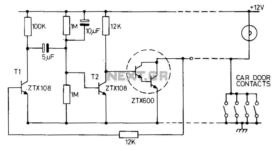
This circuit maintains the internal light for approximately one minute after the car doors are closed. When the door contacts open, a positive voltage pulse is applied to the base of transistor T1. This action activates T1, which in...
This is a short-range light barrier designed for use as an intruder alarm in doorposts and similar applications. The 555 timer in the transmitter oscillates at approximately 4.5 kHz. The short-range light barrier operates by utilizing a transmitter and a...

This is a light sensor circuit designed to detect darkness, utilizing the op-amp 741 integrated circuit as the primary control element. The circuit is straightforward and specifically designed to sense light during nighttime. The light detection is accomplished using...
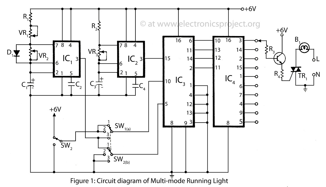
The multi-mode running light presented on this website features a simple circuit diagram designed for a bidirectional operation. It supports three different modes, making it a versatile addition to various electronics projects. The multi-mode running light circuit is designed to...

This circuit is a real core of the dimmer system. This circuit generates a ramp 100 Hz signal which is synchronized to the incoming mains voltage. The ramp signal which is generated will start from 10V and go linearly...