
Multi-Mode Running light with description

The multi-mode running light circuit is designed to provide an engaging visual effect through sequential illumination of LEDs. The circuit typically employs a microcontroller or a combination of logic gates to control the timing and sequence of the light patterns.
In a bidirectional configuration, the circuit allows for the LEDs to light up in both directions, creating a dynamic effect that enhances the visual appeal of the project. The three operational modes can be defined as follows:
1. **Sequential Mode**: In this mode, the LEDs light up one after another in a predetermined sequence. This creates a flowing effect, which can simulate movement.
2. **Alternate Mode**: This mode allows for two sets of LEDs to alternate their illumination. For instance, while one set is on, the other set remains off, and vice versa. This creates a blinking effect that can be visually striking.
3. **Simultaneous Mode**: In this mode, all the LEDs are illuminated at once. This can be useful for situations where maximum visibility is required.
The circuit may include additional components such as resistors to limit current through the LEDs, capacitors for smoothing out voltage fluctuations, and possibly transistors for driving the LEDs if higher power is needed. A power supply circuit will also be integrated to ensure consistent voltage levels across all components.
Overall, this multi-mode running light circuit is not only functional but also serves as an excellent educational tool for those looking to understand the principles of LED operation, timing control, and circuit design. It is suitable for hobbyists and professionals alike, providing a foundation for further experimentation and customization in electronic projects.Multi-Mode Running light in this website is simple with families design circuit diagram of multi-mode running light bidirectional and 3 different modes with versatile various electronics project with description. 🔗 External reference
Related Circuits
This circuit is intended to drive the various lights decorating the crib prepared during Christmas season at many homes in Latin Countries, especially for children delight, in order to obtain realistic light-effects. The circuit design for driving lights in a...

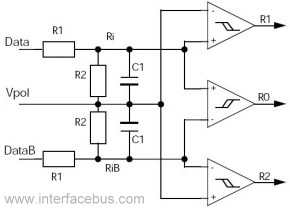
Figure 1 illustrates a simple circuit designed for converting an audio signal (such as one from the output terminals of a CD player). The circuit primarily consists of a buffer/amplifier stage and three filtering circuits: a high-pass filter, a...
The physical interface bus can be either fiber (optical) or wire (electrical). The distinction lies in the fact that the electrical interface is defined just before the optical encoder. Therefore, the physical interface bus between devices is optical (fiber),...
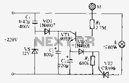
Utilize the call sheet to touch the electrical threshold M, which causes the E lamp to light up. When the same interval subparagraph is triggered, the lights will automatically turn off. A voltage regulator rectifier circuit is formed using...

This is a simple automatic light switch circuit designed for bedrooms. After construction, connect the input terminals of this circuit in parallel to the internal buzzer terminals of a quartz alarm clock. When the clock alarm is activated, the...
The circuit below uses a CMOS dual D flip flop (CD4013) to toggle a relay or other load with a momentary push button. Several push buttons can be wired in parallel to control the relay from multiple locations. More:...