
Colpitts oscillator

In an L-C (inductor-capacitor) circuit, the resonant frequency is a critical parameter that determines the frequency at which the circuit will oscillate. The resonant frequency can be calculated using the total capacitance of the circuit, which is derived from the individual capacitances of capacitors C1 and C2 connected in parallel. The formula C_total = C1C2/(C1+C2) is used to compute the total capacitance when capacitors are in parallel, allowing for an accurate assessment of the circuit's behavior at resonance.
The resonant frequency (f_r) can then be calculated using the formula:
f_r = 1 / (2π√(L * C_total))
Where L is the inductance of the inductor in the circuit. This equation shows how the resonant frequency is inversely proportional to the square root of the product of inductance and total capacitance. Understanding this relationship is essential for designing circuits that require precise frequency tuning, such as oscillators, filters, and radio transmitters. Proper calculation of the total capacitance and resonant frequency ensures optimal performance and stability of the circuit.When calculating its resonant frequency, use C1C2/C1+C2 for the total capacitance of theL-C circuit.
Related Circuits
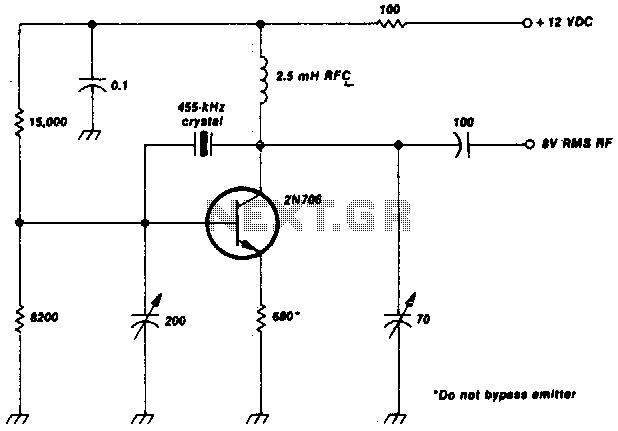
This crystal-oscillator circuit utilizes a 455-kHz crystal. It is a straightforward project. The crystal oscillator circuit based on a 455-kHz crystal operates by utilizing the piezoelectric properties of the crystal to generate a stable frequency. The circuit typically consists of...
More: The provided input lacks specific details or context regarding an electronic circuit or schematic. To create a comprehensive electronic schematic description, it is essential to include key components, their interconnections, and the overall functionality of the...
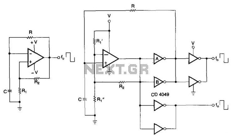
CMOS buffers added to an operational amplifier oscillator enhance performance, primarily due to the asymmetry and variability of the operational amplifier's output saturation voltages. The integration of CMOS buffers into an operational amplifier (op amp) oscillator circuit serves to significantly...
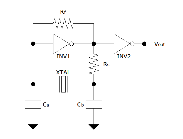
The Pierce oscillator is a simple circuit that, like the ring oscillator, utilizes inverters, though typically only one inverter is required. Its operational principle differs significantly from that of the ring oscillator, as it employs the inverter in its...
This result places the oscillator within the UK FM Band, which ranges from 87.5 to 108 MHz. If L1 is equipped with an adjustable ferrite core, its inductance can be modified, allowing for fine tuning. If L1 consists of...
The DC path is established from the negative side (ground) of VCC through RE, Q1, T1, and returns to the positive side of VCC. The figure clearly illustrates that both the AC and DC components flow through the tank...