
Oscillator Buffers

The integration of CMOS buffers into an operational amplifier (op amp) oscillator circuit serves to significantly improve overall performance by addressing issues related to output saturation voltages. Operational amplifiers are known for their high gain and versatility in analog signal processing, but they can exhibit asymmetry in their output characteristics. This asymmetry often leads to variability in the saturation voltages, which can adversely affect the stability and accuracy of the oscillator's output signal.
CMOS buffers, characterized by their high input impedance and low output impedance, can effectively isolate the op amp from the load. This isolation minimizes the impact of load variations on the op amp's performance, resulting in more consistent output levels. By buffering the output of the op amp, the CMOS buffers ensure that the oscillator can drive subsequent stages without distortion or degradation of the signal.
In addition to improving output stability, CMOS buffers can also enhance the frequency response of the oscillator circuit. Their fast switching capabilities allow for better handling of high-frequency signals, which is essential in applications requiring precise timing and waveform generation. Furthermore, the low power consumption of CMOS technology contributes to the efficiency of the overall circuit, making it suitable for battery-operated devices and other applications where power conservation is critical.
In summary, the incorporation of CMOS buffers in an op amp oscillator not only mitigates issues related to output saturation voltages but also enhances the circuit's performance in terms of signal integrity, frequency response, and power efficiency. CMOS buffers added to an op amp oscillator improve performance, largely as a result of nonsymmetry and variability of th e op amp"s output saturation voltages.
Related Circuits
Hartley Oscillator tutorial and the theory behind the design of the Hartley Oscillator, which uses an LC oscillator tank circuit to generate sine waves. The Hartley oscillator is a type of electronic oscillator that generates sine waves using an inductor-capacitor...
The RF engineer often needs an instrument that can reliably and quickly check a low-frequency quartz crystal unit. However, such equipment is challenging to find, and engineers frequently refer to electronic circuit handbooks for schematics that can perform this...
The capacitor charges until the switching voltage is reached. When the switch (SUS) is activated, the inductor causes the current to oscillate. When the current through the switch drops below the holding current, the device turns off, and the...
This application note analyzes the details of a Wien-bridge oscillator, shows how a JFET maintains oscillation, and demonstrates adding a digital potentiometer (digipot), rather than a variable resistor, to improve stability and flexibility. The Wien-bridge oscillator is a type of...
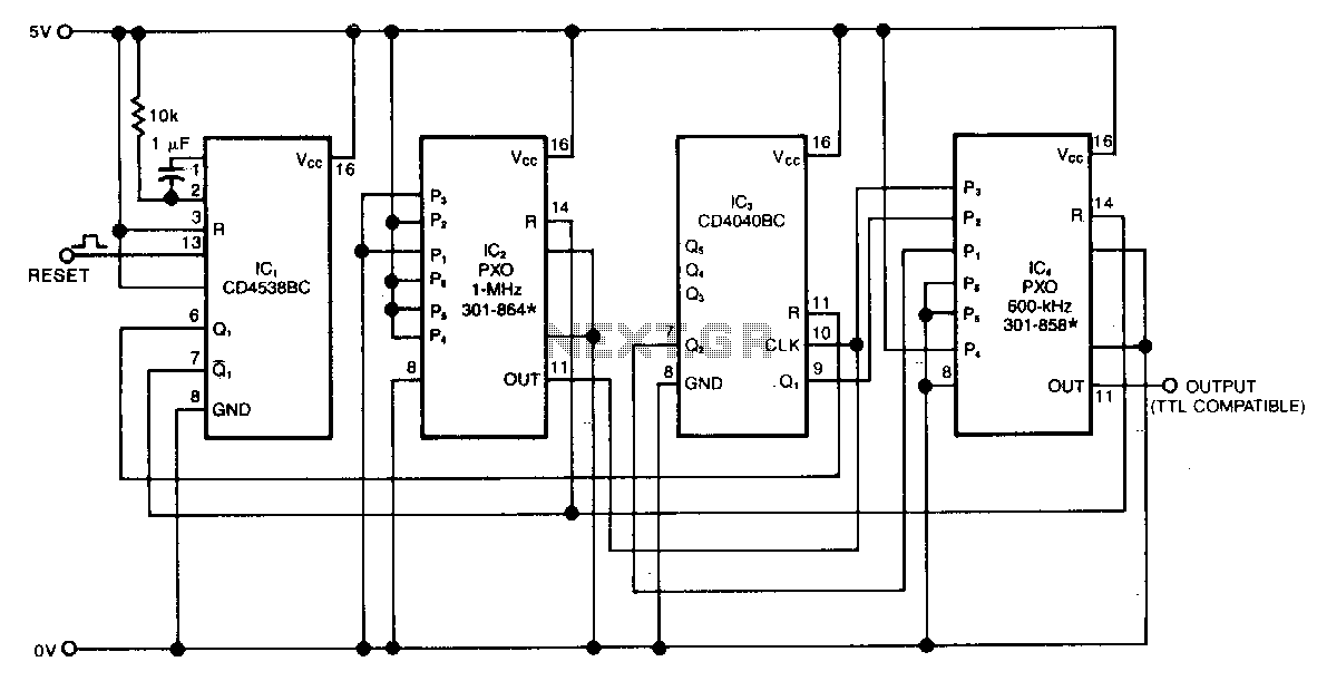
The swept-frequency oscillator provides a cost-effective source of discrete frequencies for testing digital circuits. This configuration generates an 80-second sequence of eight frequencies, with each frequency maintained for 10 seconds. The dwell time and the number of frequencies can...
The Pierce oscillator shown above is essentially a common emitter amplifier with a tuned circuit for a collector load and a quartz crystal as a feedback element. In order to determine whether the Barkhausen criteria is satisfied, loop gain...