
colpitts oscillator

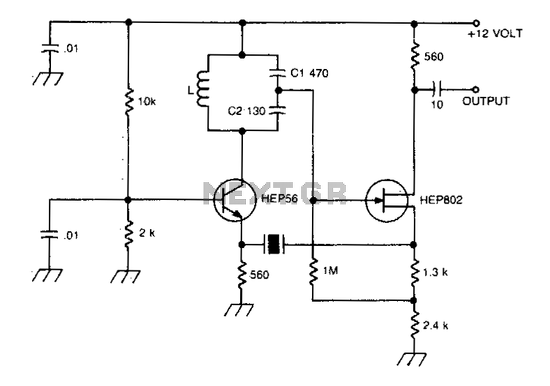
The Colpitts Oscillator is a type of electronic oscillator that utilizes a combination of an inductor (L) and two capacitors (C1 and C2) to produce an oscillating signal. The configuration typically involves an NPN transistor, which serves as the active device to amplify the signal. The feedback network, composed of capacitors C1 and C2, is critical for determining the oscillation frequency and stability of the circuit.
In this circuit, the capacitors C1 and C2 are connected in series, and their combined capacitance (CT) is calculated using the formula CT = (C1*C2)/(C1+C2). This relationship affects the overall feedback ratio, which is essential for sustaining oscillations. The inductor L is also a key component, as it, along with CT, defines the oscillation frequency through the equation f = 1/(2*pi*sqrt(L*CT)).
The design of the Colpitts Oscillator allows for the generation of sine wave signals, making it suitable for various applications, including signal generation and frequency synthesis. The choice of component values directly influences the performance characteristics, such as frequency stability, output amplitude, and phase noise. Proper simulation in environments like SimElectronics aids in optimizing these parameters before physical implementation.Simulation of Colpitts Oscillator circuit using npn transistor and other components available in SimElectronics is shown. The feedback ratio is determined by the relative values of the Capacitors C1 and C2. Frequency of oscillation is given by f = 1/(2*pi*sqrt(L*CT) where CT = (C1*C2)/(C1+C2) 🔗 External reference
Related Circuits
In this version of the oscillator, Rb is a small incandescent lamp. Typically, R1 = R2 = R and C1 = C2 = C. During normal operation, Rb self-heats to the point where its resistance is Rf/2. A Wien...
A typical Butler oscillator operating within the frequency range of 20 to 100 MHz incorporates a Field Effect Transistor (FET) in the second stage of its configuration. The circuit exhibits reliability issues when utilizing two bipolar transistors. In some...

This design circuit features a simple, cost-effective amplitude-stabilized phase-shift sine wave oscillator that requires one integrated circuit (IC) package, three transistors, and operates from a single power supply. The circuit incorporates an RC network configured for phase shift, oscillating...
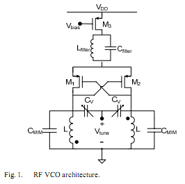
The oscillator is designed to tune from 1.8 GHz to 2 GHz for typical cellular telephony applications. An extended tuning range can be obtained by adjusting the ratio between the varactor capacitance and fixed capacitance in the tank. PMOSFETs...
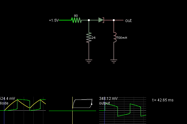
This example illustrates a tunnel diode utilized to create an oscillator. Two resistors are employed to bias the diode within its negative resistance region. As current flows through the inductor, the voltage across the tunnel diode rises until it...
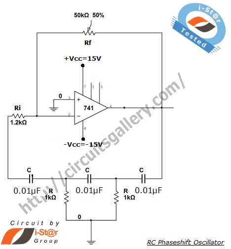
A phase-shifted oscillator can be constructed using a basic operational amplifier (op-amp), three resistors, and three capacitors. One of the resistors should be adjustable, while the other components should have the same value. This oscillator design exhibits low distortion...