
phase shift oscillator circuit

The circuit operates by generating a stable sine wave output through a combination of phase-shifted feedback and amplitude stabilization. The phase shift is achieved using a network of resistors and capacitors that create the necessary delay for oscillation. The frequency of oscillation, approximately 12 kHz, is determined by the values of the resistors and capacitors in the RC network, allowing for adjustments based on component selection.
The LM386 operational amplifier is integral to the circuit's function, providing amplification with a fixed gain, which simplifies design considerations. The 10 µF capacitor in series with the 1M resistor serves to couple the output from Q2 to the LM386 input while blocking any DC offset, ensuring only the AC component of the signal is amplified.
The rectification process at the output of the LM386 converts the AC signal into a DC voltage, which is stored in the 5 µF capacitor. This stored voltage is crucial for controlling the base of Q3, allowing it to modulate the current that flows through Q1. The emitter follower configuration of Q1 ensures that the oscillator is driven with a stable voltage, thereby enhancing the overall stability of the sine wave output.
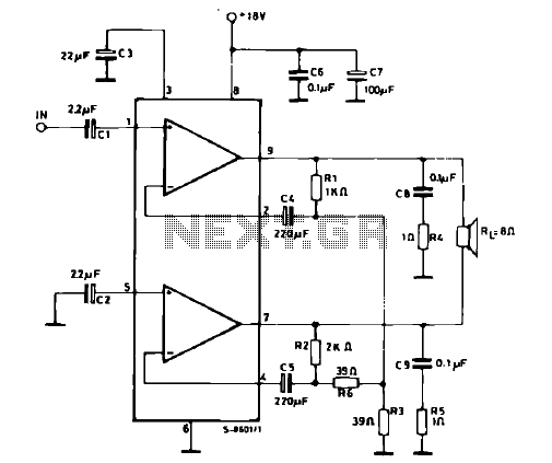
In summary, this circuit exemplifies an efficient design for generating a stable sine wave output using minimal components, making it suitable for various applications where a reliable signal source is required. The careful selection of components and their arrangement within the circuit ensures both amplitude stability and frequency accuracy.This is a design circuit of a simple inexpensive amplitude stabilized phase shift sine wave oscillator which requires one IC package, three transistors and runs off a single supply. This circuit is combination with the RC network comprises a phase shift configuration and oscillates at about 12 kHz.
The remaining circuitry provides amplitude stabil ity. Here`s the schematic figure of the circuit. The high impedance output at Q2s collector is fed to the input of the LM386 via the 10 F-1M series network. This circuit is using op amp LM386 causes it has fixed gain of 20. The 1M resistor in combination with the internal 50 k © unit in the LM386 divides Q2s output by 20. The positive peaks at the amplifier output are rectified and stored in the 5 F capacitor. This potential is fed to the base of Q3. Q3s collector current will vary with the difference between its base and emitter voltages. Since the emitter voltage is fixed by the LM313 1. 2V reference, Q3 performs a comparison function and its collector current modulates Q1s base voltage.
Q1, an emitter follower, provides servo controlled drive to the Q2 oscillator. 🔗 External reference
Related Circuits
This is a simple electronic siren circuit that can be utilized in various applications where a siren sound is necessary. The circuit is straightforward, employing only two transistors and a few additional components, and it will produce a siren...
This circuit prioritizes a microphone and preamplifier (voice circuit) over any other audio signal, functioning similarly to a one-way intercom. When the push-to-talk switch is activated, the main amplifier switches from music to the voice signal. Essentially, a voice-over...
In this figure, S1 initiates the timing process, and once the timer is activated, toggling this switch will not impact the timing operation. S2 serves as the OFF switch located in the center; toggling this switch allows the timer...
The schematic illustrates a 12 W Bridge Amplifier circuit diagram utilizing the TDA2007A, a class AB dual audio power amplifier. This amplifier is specifically designed for stereo applications in music centers, television receivers, and portable radios. As stated in...
Connect the diode VD under test to sockets X1 and X2. A stabilized power supply applies reverse breakdown voltage to VD, allowing the stabilized voltage value Uz to be read from voltage meter V. The stable operating current value...
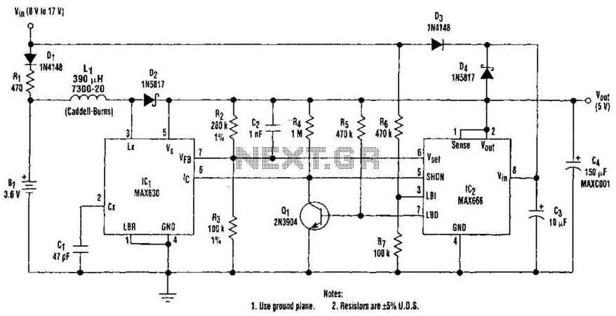
A 9-V wall adapter supplies Vm. IC2 contains a low-battery detector circuit that senses l7IN through resistors R6 and R7. The detector output at pin 7 drives an inverter (Q1), which in turn controls the shutdown inputs of IC1...