
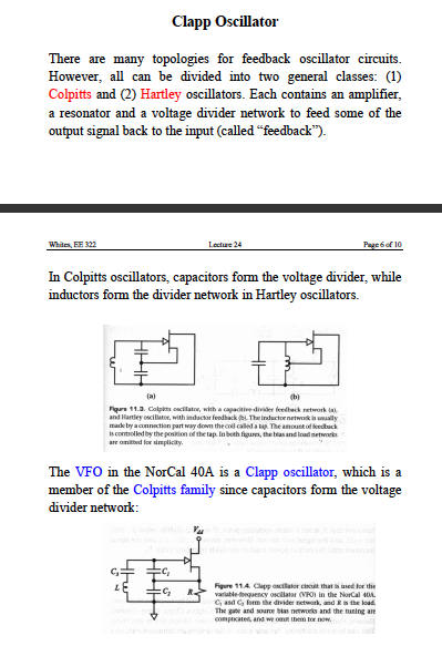
colpitts oscillators

The Colpitts oscillator is a type of electronic oscillator that generates sinusoidal waveforms, commonly used in radio frequency applications. The circuit typically comprises an LC tank circuit formed by the inductor and capacitors, which determines the oscillation frequency. The feedback mechanism provided by the capacitors Cfb-a and Cfb-b is crucial for sustaining oscillations, as it ensures that a portion of the output signal is fed back into the input in phase with the original signal.
In practical applications, the selection of the inductor and capacitors is critical. The inductor's value influences both the frequency of oscillation and the circuit's quality factor (Q). A higher Q indicates lower energy loss, resulting in more stable oscillations. The capacitors, particularly the feedback capacitors, must be chosen to match the impedance requirements of the circuit while minimizing the effects of parasitic capacitance that can degrade performance.
When designing a Colpitts oscillator, it is essential to account for the operating frequency range and the desired tuning capabilities. The use of variable capacitors allows for fine-tuning of the oscillator's frequency, making it adaptable for various applications. The calculated values for capacitors and inductors must be verified through simulation or prototyping to ensure the oscillator performs as intended across the specified frequency range.
In summary, the Colpitts oscillator is a versatile and effective circuit for generating oscillations, with careful attention to component selection and circuit design being paramount to achieving optimal performance.Colpitts oscillators are somewhat similar to the shunt fed Hartley circuit except the Colpitts oscillator, instead of having a tapped inductor, utilises two series capacitors in its LC circuit. With the Colpitts oscillator the connection between these two capacitors is used as the centre tap for the circuit.
Perhaps the simplest Colpitts oscillato r to construct and get running is the "series tuned" version, more often referred to as the "Clapp Oscillator". Because there is no load on the inductor a high "Q" circuit results with a high L/C ratio and of course much less circulating current.
This aids drift reduction. Because larger inductances are required, stray inductances do not have as much impact as perhaps in other circuits. Rather than present designs for specific frequencies for the Colpitts Oscillator we have submitted a schematic which may be "impedance" scaled to any frequency.
Simply convert the suggested reactances back to the required inductor and capacitances at your band of interest. The Colpitts oscillator inductor should be around 250 - 300 ohms and the "NET" capacitive reactance should total around the same.
Feedback capacitors Cfb, both "a" and "b" are each in the region of 45 ohms leading to very large values which is very helpful in swamping out the capacitive effects of the transistor used. The total capacitive reactance of the parallel combination of capacitors depicted as series tuning below the inductor in a series tuned Colpitts oscillator or "Clapp oscillator" should have a total reactance of around 200 ohms.
Not all capacitors may be required in your particular application. Pay particular attention to our comments in Oscillator Basics. Perhaps the best approach to values used for tuning a Colpitts oscillator might be to give a practical example. Consider constructing an oscillator which tunes part of the 40M amateur radio band, 7. 0 - 7. 2 Mhz. Now that is a frquency ratio of 1. 02857 requiring a modest net capacitance variation of 1. 058. If that is not understandable go back to our basics. Using an inductor of 300 ohms at 7 Mhz for our Colpitts or Clapp oscillator yields a value of about 6.
8 uH. Each Cfb at 45 ohms works out at 500 pF so we will try 470 pF. Using an inductor of 6. 8 uH requires a total capacitance of 76 pf to resonate at 7. 0 Mhz. At 7. 2 Mhz this value has dropped down to 71. 86 pF a small variation. Effectively all the capacitors are in series in a Colpitts oscillator. That is Cfb-a and Cfb-b are each in series with the total parallel combination below the inductor. Given Cfb are each 470 pF what values are the parallel combination to achieve outcomes of net 76 pF and 71. 86 pF Had you done basics and in particular capacitance you would know the answer. We`re not being smart here just pointing out there is no such thing as a "free" lunch, you have to know "the basics".
Having done these lectures on the internet for several years, yes I`m Ian Purdie VK2TIP, I don`t appreciate email questions from lazy students expecting me to complete or provide their assignments for them. Do some work for yourself!. Back to our Colpitts oscillator, I`ll give you a "FREE" clue to the answer with these colourful formulas for the answer in figure 3.
I know a shorter method. See this example in capacitance. Here in our Colpitts oscillator Ctotal-max is the maximum of the parallel combination including the variable capacitor Cv, set at maximum while Ctotal-min is the same combination with Cv set at minimum. Clear on that Note that the other series capacitor depicted in line with Cv in figure 2 may or may not be required in your particular application.
Anyhoo! your calculations should have yielded a Cmax of 112. 3 and Cmin of 103. 51. Now that is a pretty tiny swing, so you can see the possible need for a series capacitor with Cv if all you have available is a fairly high value Cv. Let`s assume Cv is 5 - 25 pf (a variation of 20 pF) and C 🔗 External reference
Related Circuits
The input and output impedance, along with load and source resistance, are significantly interdependent in a common collector (CC) circuit. This interdependence is why impedance matching does not yield representative results for circuit operation. Analyzing the circuit as a...

An early schematic of a Colpitts circuit utilizing a vacuum tube, redrawn from a patent publication. The Colpitts oscillator, invented in 1920 by American engineer Edwin H. Colpitts, is one of several designs for electronic oscillators. The Colpitts oscillator is...
The circuit serves as a foundational design, requiring experimentation for specific applications. In popular microwave bands, local oscillators (LOs) are typically generated using overtone crystal oscillators followed by multipliers. A table presents the standard LO frequencies for narrowband segments,...
A linear feedback amplifier that incorporates reactive elements can produce sinusoidal oscillations at a frequency where the loop gain Ab equals -1. The sine wave oscillators examined in this experiment comprise two interconnected components: the amplifier section and the...
In order to generate a single note you may try these simple circuits. With only three components you may implement some basic buzzers. You need a telephone earpiece for the first circuit. Any old telephone set has got one...
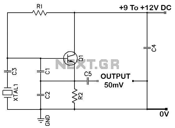
Colpitts 1 MHz to 20 MHz Crystal Oscillator Circuit. This is a simple Colpitts crystal oscillator for frequencies ranging from 1 to 20 MHz. The parts list includes: R1 - 220 kΩ, R2 - 1 kΩ, C1 - 82...