
Colpitts oscillator

The Colpitts oscillator is a type of electronic oscillator that generates sine waves and is characterized by its use of a combination of capacitors and an inductor in its feedback network. The fundamental operation of the Colpitts oscillator relies on the resonant frequency determined by the inductor and the capacitors connected in series.
In this particular schematic, the vacuum tube serves as the active element, providing the necessary gain for oscillation. The circuit typically consists of a vacuum tube, an inductor (L), and two capacitors (C1 and C2) arranged in a voltage divider configuration. The output frequency can be adjusted by varying the values of the capacitors or the inductor, allowing for flexibility in frequency generation.
The feedback loop is crucial for sustaining oscillations. It is established through the coupling of the output from the anode of the vacuum tube back to the junction of the two capacitors. This feedback ensures that the circuit maintains its oscillation at the resonant frequency determined by the LC network.
The Colpitts oscillator is known for its stability and is often used in applications requiring precise frequency generation, such as in radio transmitters and receivers. Its design can be modified to include additional components, such as resistors for biasing the vacuum tube and improving linearity, or additional filtering stages to enhance signal purity.
Overall, the early schematic of the Colpitts circuit showcases the foundational principles of oscillator design that remain relevant in modern electronic applications.Early schematic of a Colpitts circuit, using a vacuum tube, redrawn from the patent publication. A Colpitts oscillator, invented in 1920 by American engineer Edwin H. Colpitts, is one of a number of designs for electron.. 🔗 External reference
Related Circuits
Signals with a known frequency but an unknown phase can be detected using an in-phase signal and a signal that is shifted by 90 degrees, a method commonly utilized in lock-in amplifiers, synchronous detectors, and frequency-response analyzers. The signal...
A question has been raised regarding the type of oscillator found on Wikipedia, specifically referring to the NPN Colpitts oscillator as illustrated in the image titled "File:NPN Colpitts oscillator collector coil.png." The NPN Colpitts oscillator is a type of electronic...

This circuit is an oscillator utilizing astable mode operation, based on the 555 timer integrated circuit (IC). It functions as a free-running oscillator. The operation begins when the capacitor (C) charges towards 2/3 of the supply voltage (V+) through...
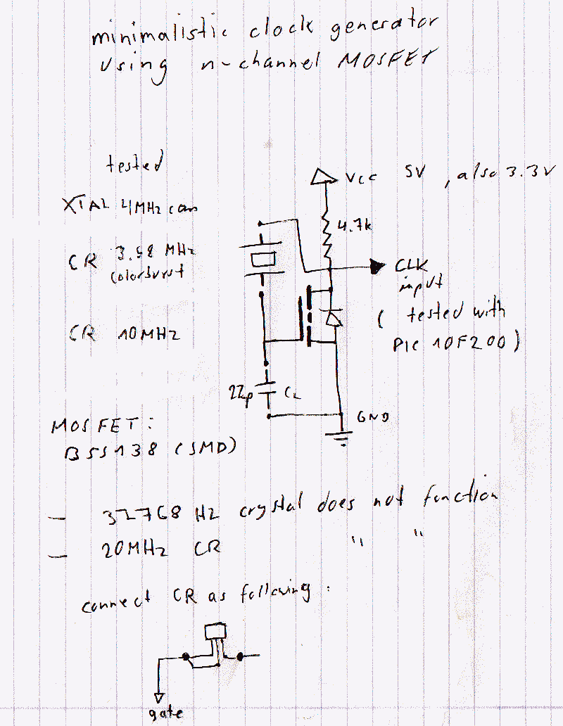
This is the first post discussing a watch crystal oscillator for a PIC microcontroller. The intention is to avoid the use of logic gates in the circuit. A watch crystal oscillator is a fundamental component used in various electronic applications,...
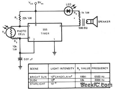
This circuit's frequency of oscillation increases directly with light intensity. The greater the light intensity, the higher the frequency of the oscillator. The 555 timer operates in astable oscillator mode, where frequency and duty cycle are controlled by two...
A crystal oscillator circuit comprises various gates as illustrated in the provided figures. Figure (A) represents a crystal oscillator circuit operating at 1 MHz, while figure (B) depicts a 20 MHz crystal oscillator circuit. Figure (C) shows a variable...