
Comb electric circuit

The comb electric circuit operates by utilizing a dual-temperature control system, allowing users to select between low (L) and high (H) temperature profiles via switch S. This functionality is critical for accommodating various hair types and styling needs. When the switch is engaged, current flows through the heating elements, EH1 or EH2, which are strategically positioned to efficiently transfer heat to the hair.
The circuit employs a rectifier to convert the incoming 220V AC supply into a stable DC output. This rectification is essential for powering the small DC motor M, which drives the mechanical components of the comb. The motor's rotation is synchronized with the heating elements, ensuring that heat is applied consistently during the styling process.
The heating wires are designed to reach the desired temperature quickly, thanks to their low thermal mass and high conductivity. The circuit may also include thermal protection features to prevent overheating, ensuring safety during operation. Additionally, an LED indicator may be incorporated to signal when the device is powered on and heating.
Overall, this comb electric circuit exemplifies a practical application of electronics in personal grooming devices, combining heating and mechanical motion to facilitate effective hair styling. Comb electric circuit shown in Figure 1-3. It has two temperature options, switch S into L or H profile file, you can get different temperatures. Then later on switch S, the ci rcuit is turned on, the heating wire EH1 or EH2 heating, after UR rectification, the 220v alternating current into direct current, so that a small DC motor M is rotated. Heat into the hair, to shaping hair.
Related Circuits
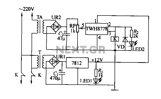
An electric power limiter circuit restricts the user load, ensuring that household appliances operate within a specified normal current range. When the load exceeds a predetermined threshold, the power supply is disconnected. This circuit utilizes the high-power integrated TWH8778...
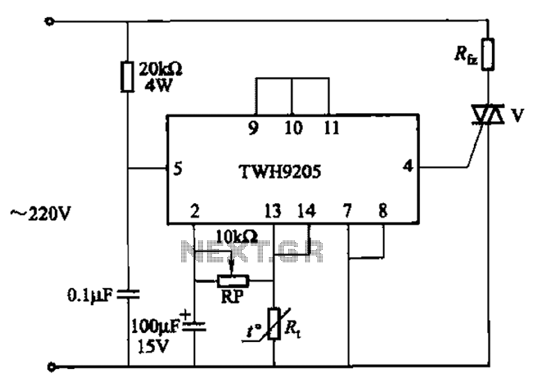
This circuit is used for temperature control in various heating equipment such as water heaters, microwave ovens, air conditioners, refrigerators, fans, and automatic fire extinguishing devices. It includes a negative temperature coefficient (NTC) thermistor as the temperature sensing element...
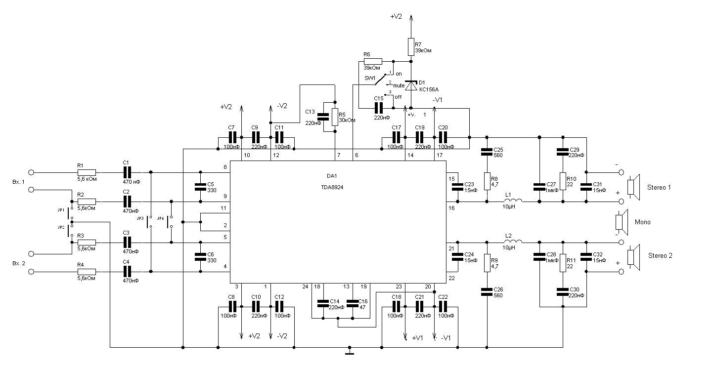
240W power amplifier circuit based on the TDA8924 class D design. This integrated circuit features short-circuit protection at the output, thermal protection, and safeguards against acoustic damage from inrush currents during power on and off. The schematic allows for...
A 12V to 20000V inverter circuit diagram (stun gun) is presented. This circuit generates a very high voltage and must be used with caution to prevent electric shock. The transformer can produce over 1000V and amplify the voltage by...
Electrical lines that include lighting circuits originate from the main distribution panel of the installation. Each line consists of three conductors: phase, neutral, and ground. All three conductors extend to the terminal point of each luminaire, and if the...
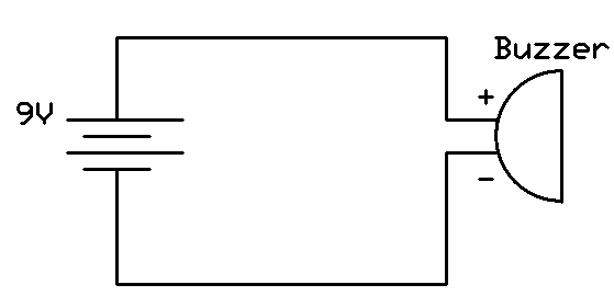
This project involves connecting the positive terminal of the battery to the positive lead of the buzzer and the negative terminal of the battery to the negative lead of the buzzer. Typically, the positive lead of the buzzer is...