
Buzzer Circuit
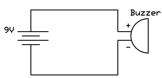
In this simple circuit, the buzzer serves as an output device that generates sound when powered by a direct current (DC) source, such as a battery. The battery provides the necessary voltage and current to activate the buzzer.
To construct the circuit, ensure that the battery voltage matches the operational voltage of the buzzer to prevent damage. The most common types of buzzers are piezoelectric and electromagnetic, each requiring specific voltage ratings. The positive lead, often marked in red, should be connected to the positive terminal of the battery, ensuring a secure connection to facilitate proper operation. Conversely, the negative lead, typically black, should be connected to the negative terminal of the battery.
It is essential to verify the polarity before powering the circuit, as reversing the connections can lead to malfunction or permanent damage to the buzzer. The circuit can be tested by briefly connecting the battery; if the buzzer emits sound, the connections are correct. For added safety and functionality, consider incorporating a switch in series with the buzzer to allow for easy control of the sound output without needing to disconnect the battery.In this project, all we do is hook up the positive side of the battery to the positive lead of the buzzer and the negative side of the battery to the negative lead of the buzzer. The positive lead of the buzzer many of the times is a red color and the negative lead of the buzzer is usually a black color.
🔗 External reference
Related Circuits
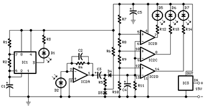
All distances mentioned can vary depending on the infrared transmitting and receiving LEDs used and are significantly affected by the color of the reflecting surface. Black surfaces greatly reduce the device's sensitivity. This circuit can also be applied in...
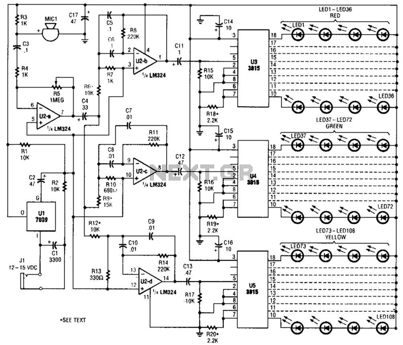
The microphone input, MIC1, is connected through capacitor C3 and resistor R4 to the inverting amplifier U2-a, where the gain of U2-a is adjusted by potentiometer R5. The output from U2-a is passed through capacitor C4 to the remaining...
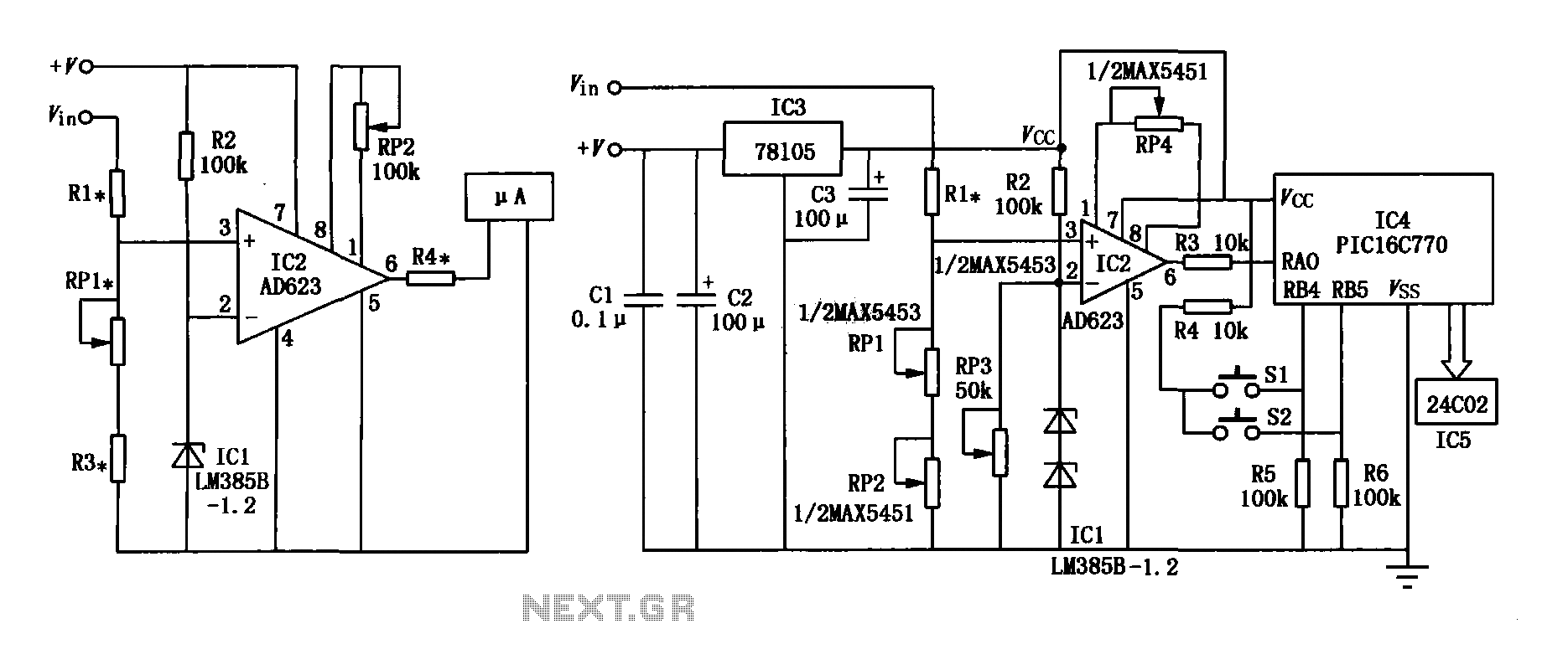
The range precision voltmeter electrical schematic is depicted in Figure (a) below. It features an amplifier circuit and several high-precision components that significantly enhance the performance range of the voltmeter. The inverting input of the instrumentation amplifier AD623 (IC2)...
The input impedance of AC-coupled operational amplifier (op-amp) circuits is primarily determined by the resistance that establishes the DC operating point. When using CMOS op-amps, the input impedance is high, reaching up to 10 MΩ in current op-amps. For...
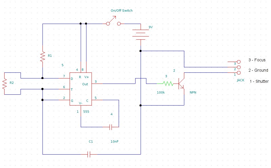
This document provides information on constructing a DIY time-lapse circuit that enables a camera to automatically capture images at specified time intervals. These images can then be compiled to create a time-lapse film. The circuit utilizes a 2.5 mm...
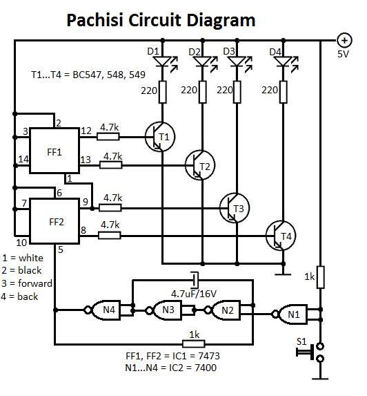
The Pachisi game is designed for two players. Each player has one figurine, which is initially placed on positions indicated by arrows on the game board. The Pachisi game, often referred to as the "Royal Game of India," is...