
Combining the Composite Sync to the Green Signal

The described circuit effectively addresses the integration of composite sync signals with RGB signals in video applications where low-cost decoders are used. The MAX9589, a high-speed video amplifier, plays a crucial role in this process. It not only combines the sync signal with the green channel but also ensures that the output maintains the integrity of the RGB signals. The circuit operates by accepting the RGB inputs and the composite sync signal and processing them to produce a synchronized output suitable for the video decoder.
The implementation involves connecting the green channel input and the composite sync input to the MAX9589. The device's internal architecture allows for the addition of the sync signal to the green channel without distorting the original RGB signals. The output from the MAX9589 is then fed into the video decoder, which can interpret the combined signal correctly.
This configuration is particularly advantageous in applications where space and cost are constraints, as it minimizes the need for additional components while enhancing performance. The anti-aliasing filtering capability of the MAX9589 is particularly beneficial, as it reduces potential artifacts in the video signal, leading to clearer and more stable image quality. This feature is essential in maintaining high video fidelity, especially in standard-definition applications where signal integrity is paramount.In some video applications, the signal sources deliver RGB signals and a composite sync signal. The RGB signals contain no video sync. At the receiver side, some low-cost video decoders do not have a stand-alone composite sync input; they only accept the sync signal with the video signal. Adding the sync signal onto the green channel for such an a pplication requires a "sync on green" circuit. There is a simple, low-cost way to add the composite sync onto the green channel for standard-definition video. The circuit in Figure 1 uses the MAX9589 to add the composite sync to the green channel, and generates the standard RGB signals at each output.
For example, consider a 0. 7VP-P green signal input and a 0. 3V composite SYNC signal input from the video sources that have 75 © terminations. From Figure 1 the output signal at the green channel after the MAX9589 is 1VP-P. For the 0. 7VP-P R and B input signals from the source, the output signals after the MAX9589 are 0. 7VP-P. There is an advantage to using the MAX9589 in this application. The MAX9589 can be used as an anti-aliasing filter in front of the video decoder and, thus, improves the video performance. 🔗 External reference
Related Circuits
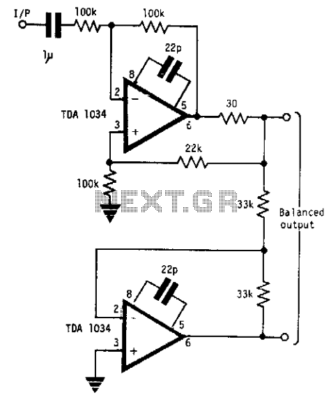
This circuit will handle +24 dBm with ± 12 volts supply using TDA 1034s. This circuit uses current and voltage feedback. The described circuit utilizes the TDA 1034S integrated circuit, which is designed for audio applications and can handle an...
The TA2003PG and TA2003FG are integrated circuits designed for AM/FM radio applications. These ICs facilitate AM/FM radio functionality, including FM front-end and AM/FM intermediate frequency processing. When combined with the TA7368P mono power amplifier IC, a comprehensive AM/FM radio...
Strain-gauge sensors convert strain into an electrical signal for applications in pressure sensors, weight measurements, force and torque measurements, and materials analysis. A strain gauge functions as a resistor, with its resistance value changing in response to strain. Strain-gauge sensors...
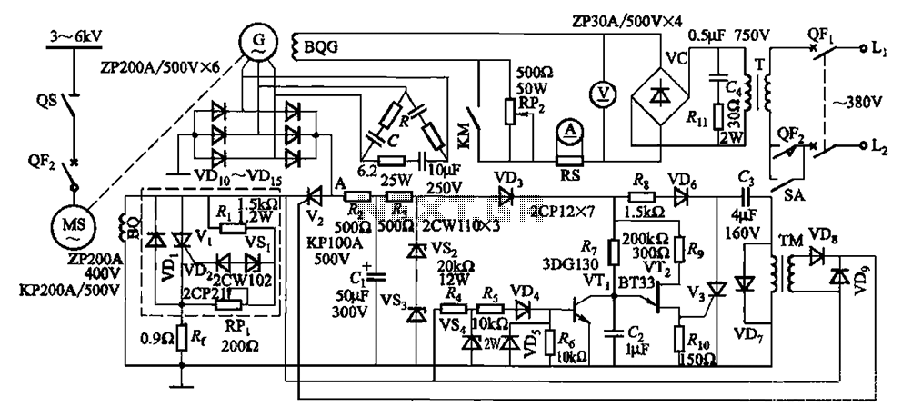
The circuit depicted in Figure 16-105 illustrates a synchronous motor. The components include BQ, which represents its field winding, and G, which denotes the AC excitation for the motor. The notation BQG indicates the field winding, with an empty...
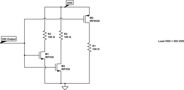
A variable frequency, variably duty cycle 555 configuration is set up in astable mode. A set of potentiometers is utilized to achieve a wide range of control. The output is functioning well; however, there is an issue. The circuit...
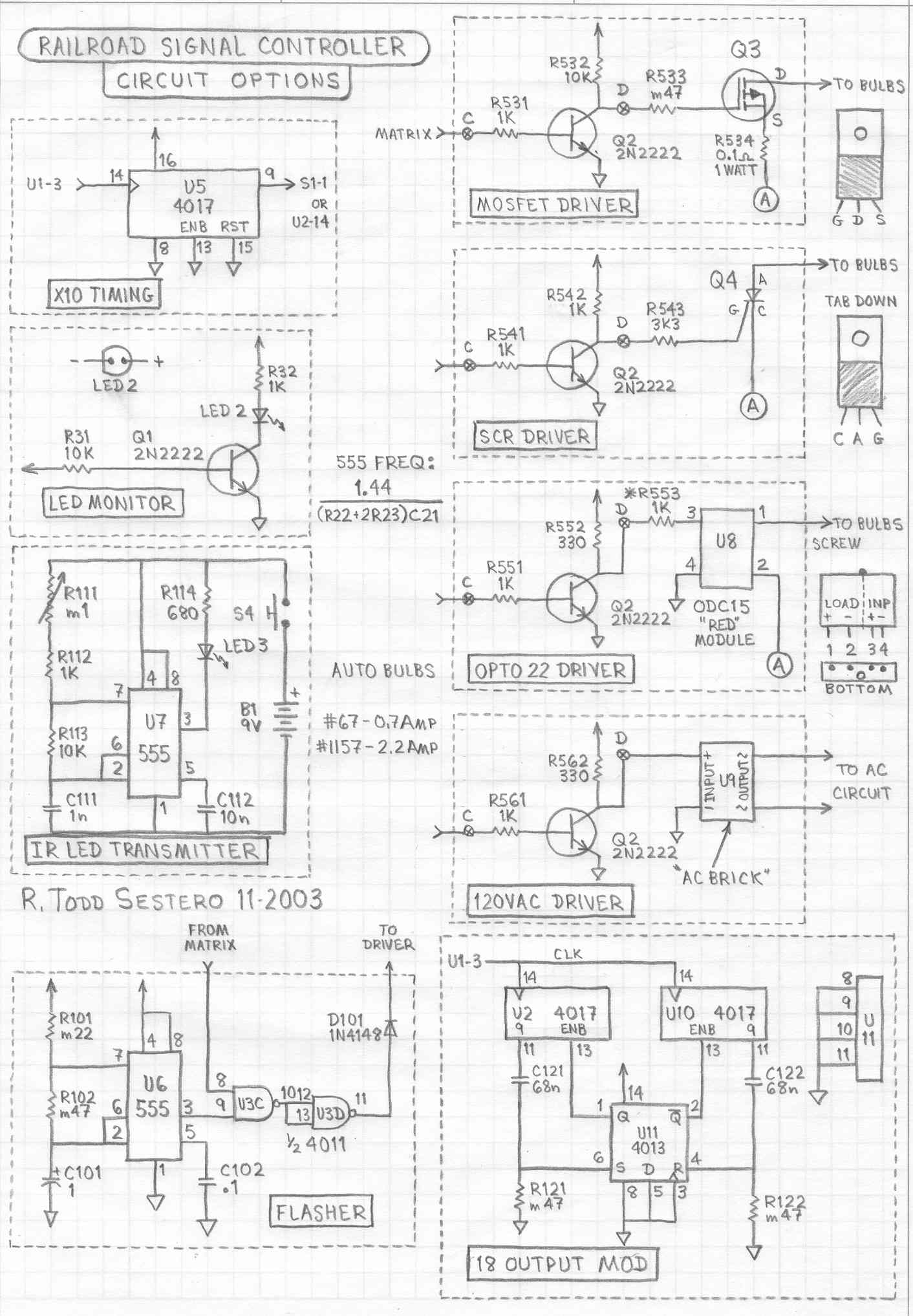
This circuit is designed to illuminate a single prototype railroad signal. It can be utilized for driving a model railroad signal, but it is intended solely for static displays and is not compatible with DCC systems, computers, or similar...