
One synchronous motor thyristor excitation circuit

The synchronous motor circuit operates by utilizing alternating current (AC) to energize the field winding (BQ) while maintaining synchronization with the supply frequency. The AC excitation (G) is crucial as it generates the magnetic field required for the motor's operation. The interaction between the stator's rotating magnetic field and the rotor's magnetic field allows the motor to maintain a constant speed, which is determined by the frequency of the AC supply.
The de-excitation process, represented by the empty box in the circuit, is essential for controlling the motor's operation during various load conditions. When the motor is required to reduce speed or stop, the de-excitation mechanism reduces the current flowing through the field winding, allowing for a smoother transition and preventing sudden changes that could damage the motor or connected equipment.
In summary, the schematic provides a clear representation of the synchronous motor's operational principles, highlighting the importance of the field winding and AC excitation in maintaining consistent performance and the role of de-excitation in managing motor behavior under different operational scenarios. Circuit shown in Figure 16-105. Figure, MS synchronous motor. BQ its field winding; G AC excitation hair motors, BQG its field winding {empty box as part of the de-excitation.
Related Circuits
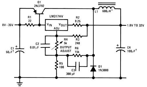
The circuit diagram of this LM317 power supply electronic project requires a few external components. The input voltage for this project must be between 8 and 35 volts, providing a variable output voltage ranging from 1.8 volts to 32...
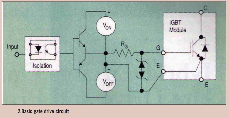
High power IGBT modules utilize hybrid integrated circuit (IC) gate drives that incorporate protection circuits, which implement desaturation detection or real-time control. High power Insulated Gate Bipolar Transistor (IGBT) modules are essential components in various high-efficiency power conversion applications, such...
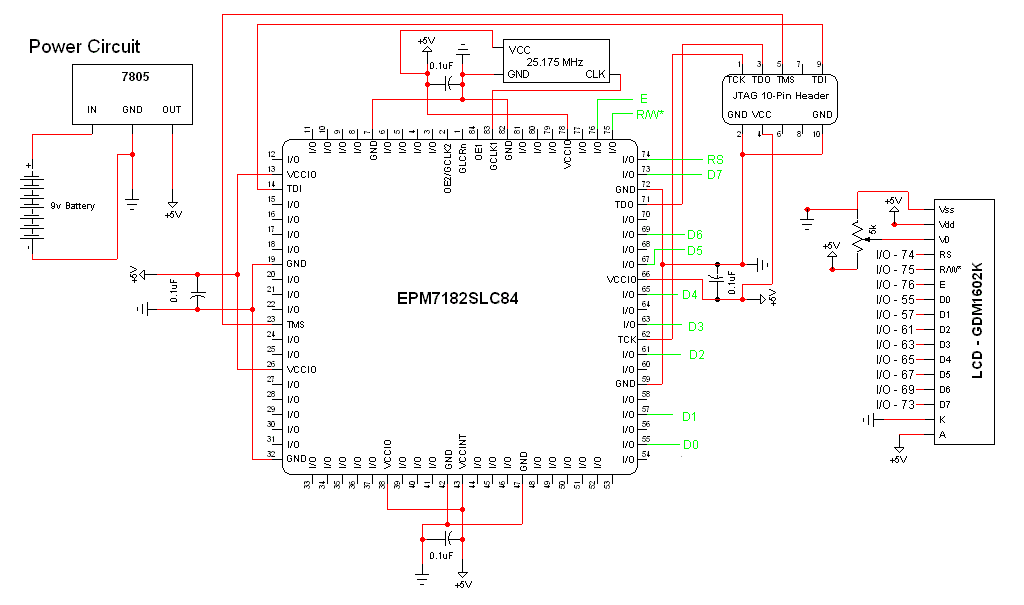
The schematic for this project is a modified version of the CPLD development board schematic. Several new components have been added for this project, and the completed schematic is presented below. The primary components in the schematic include the...
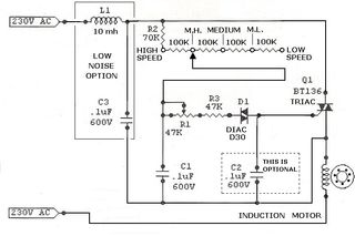
A small scroll saw is intended to be equipped with a cost-effective speed controller. The saw operates using an AC motor that seems to be brushless based on the examination conducted during disassembly. To design a speed controller for an...
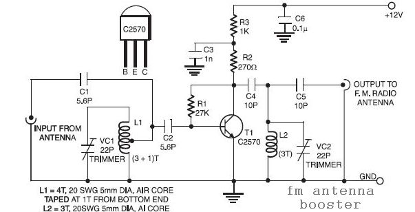
The input coil L1 is composed of four turns of 20 SWG enamelled copper wire, wound slightly spaced over a 5mm diameter former. It is tapped at the first turn from the ground lead side. Coil L2 is similar...
TV video signal processor circuit. The ECG1064 chip includes a primary video amplifier, two sync pulse amplifiers, a look-out protector, a noise detector, two noise gates, an automatic gain control (AGC) detector, an intermediate frequency (IF) AGC amplifier, a...