
Combustible gas alarm circuit diagram 7812 7805 555

The described circuit operates by integrating multiple components to create a reliable gas detection and alarm system. The buck rectifier converts the AC voltage from the transformer into a stable DC voltage suitable for powering the circuit. The voltage regulators (IC3 and IC4) ensure that the circuit operates within safe voltage levels, providing 12V and 5V outputs respectively for various components.
The gas sensor, either the QM-N5 or MQ-N type, is sensitive to specific flammable gases. It functions by changing its resistance in response to the concentration of gas in the environment. The comparator circuit, using the LM393, continuously monitors the voltage generated by the gas sensor. When the gas concentration rises above the defined threshold, the comparator's output transitions from low to high, activating the alarm system.
The 555 timer, a versatile integrated circuit, is configured in astable mode to generate a square wave output. The frequency of oscillation is determined by the values of resistors R3 and R4, and capacitor C1, allowing for flexibility in tuning the alarm frequency. The output from the 555 timer is used to drive the speaker, producing an audible alarm at 1 kHz, which is significant enough to alert individuals nearby. The LED serves as a visual indicator, providing an additional layer of notification.
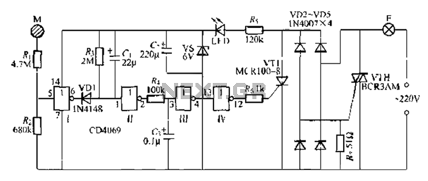
In summary, this gas detection alarm circuit is a well-designed system that effectively combines various electronic components to ensure timely alerts in the presence of flammable gases, enhancing safety in environments where such gases may pose a risk. As shown in FIG alarm by a buck rectifier and voltage regulator circuit, gas sensor, comparator circuit and sound the alarm circuit. Buck regulator circuit by a transformer rec tifier and B, the bridge rectifier circuits QL, IC3 (7812), IC4 (7805) and other components. Gas-sensitive semiconductor sensor QM-N5-type or MQ-N-type devices. Comparator IC1 dual voltage comparator LM393. Audio alarm circuit consists of IC2 (555), speaker Y, LED and other components. When the concentration of flammable gas exceeds a certain value, between AB pole semiconductor gas device resistance becomes small, the partial pressure of the resistance R1 increases, the potential of the corresponding comparator IC1 foot rises, and when the above feet when the reference voltage value, IC1 output high, the 555 set, while 555 and R3, R4, C1 composed of the oscillator starts oscillation frequency f 1.44/(R3 + 2R4) C1, as shown in FIG. parameters corresponding to a frequency of about 1000Hz. 555 signal output pin push speaker Y issued lkHz sound alarm signal, and the LED lamp flashes. When the concentration of flammable gas is normal, between the AB QM-N5 resistance becomes very large, the partial pressure resistor R1 becomes smaller, the potential reduction of the corresponding IC1 foot, IC1 output low ( 0.7V), 555 Reset, the alarm circuit does not occur.The alarm circuit sends out the concentration of flammable gas is higher than 0.04% audible and visual alarm signals to alert the owner attention.
Related Circuits
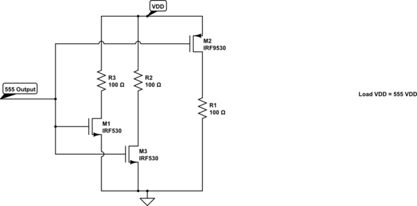
A variable frequency, variably duty cycle 555 configuration is set up in astable mode. A set of potentiometers is utilized to achieve a wide range of control. The output is functioning well; however, there is an issue. The circuit...

Figaro manufactures sensors that can detect various types of gases (e.g., hydrogen, methane, carbon monoxide, etc.). A simple circuit has been designed around the Figaro LPM2610 module, which will activate an alarm if the level of liquefied petroleum gas...

This three-band equalizer circuit functions as an active filter network for bass, mid, and high audio frequencies. It is built around the LM833 operational amplifier from National Semiconductors. The output of this three-way graphic equalizer is configured to be...
The CD4069 is a digital integrated circuit that utilizes boron to delay the activation of a light touch. It employs a j-wire connection force method and can directly replace a standard light switch without requiring changes to the existing...
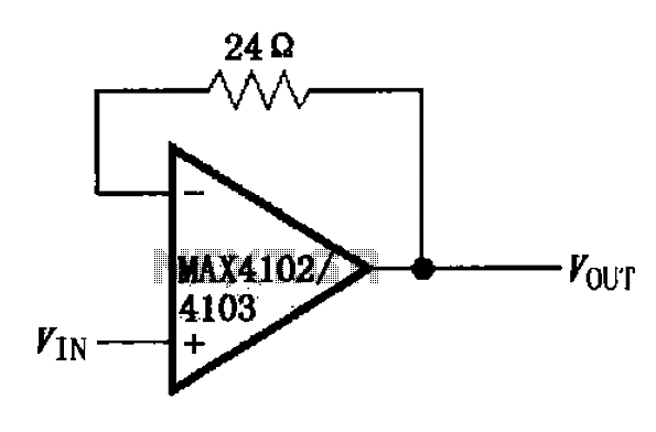
The MAX4102/4103 unity gain buffer circuit is illustrated in the figure. This circuit incorporates a small resistor (24 ohms) positioned in the feedback loop of the amplifier, which forms a unity gain buffer. Additionally, it achieves a maximum bandwidth...

This fast circuit is compatible with any amplifier that has a line or high-level input (radio, CD) that allows mixing signals from a microphone with a chosen music source and adding adjustable sound effects to the voice. The circuit...