
command line interface

The described setup consists of an mbed microcontroller, a PS/2 keyboard, and an LCD display, forming a flexible interface management system. The mbed microcontroller serves as the central processing unit, executing the commands received from the keyboard and managing the output to the LCD.
The PS/2 keyboard is connected to the mbed via a specific set of pins configured to handle serial communication. The keyboard sends keystrokes as encoded signals, which the mbed interprets using a dedicated library that handles the PS/2 protocol. This allows users to input commands that dictate how the mbed should allocate its pins.
The LCD, which is typically interfaced using either a parallel or serial communication method, displays feedback and status messages to the user. This visual output is crucial for user interaction, providing real-time information about the current pin assignments and any changes made through keyboard commands.
The core functionality of the system revolves around a command parser that interprets user inputs according to a predefined set of rules. These rules dictate how commands are structured and how they correspond to specific actions, such as assigning a pin to a particular function or reassigning it. The flexibility of this setup allows users to dynamically change the configuration of the mbed without the cumbersome process of recompiling and uploading new code, significantly enhancing development efficiency.
To implement this system, the mbed's GPIO (General Purpose Input/Output) pins are initially configured to a default state. As commands are issued through the PS/2 keyboard, the command parser updates the pin configurations in real-time, ensuring that the mbed's functionalities can be adapted to various applications, from simple input/output tasks to more complex interfacing with sensors and actuators.
Overall, this setup exemplifies an efficient and user-friendly approach to managing microcontroller pin assignments, suitable for rapid prototyping and development in embedded systems.This setup allows you to allocate the pins of an mbed for a specified interface without having to recompile the code. It uses a PS/2 Keyboard as an input device and an LCD as an output device. It can take commands and interpret them according to predefined rules in order to assign/reassign different pins for different interfaces.
🔗 External reference
Related Circuits
This page investigates a simple PA for 50MHz. This power amplifier will boost a low-level signal about 10-20mW to over 100mW. The power consumption will yet be quite low. At the bottom of this page, a complete transmitter based...
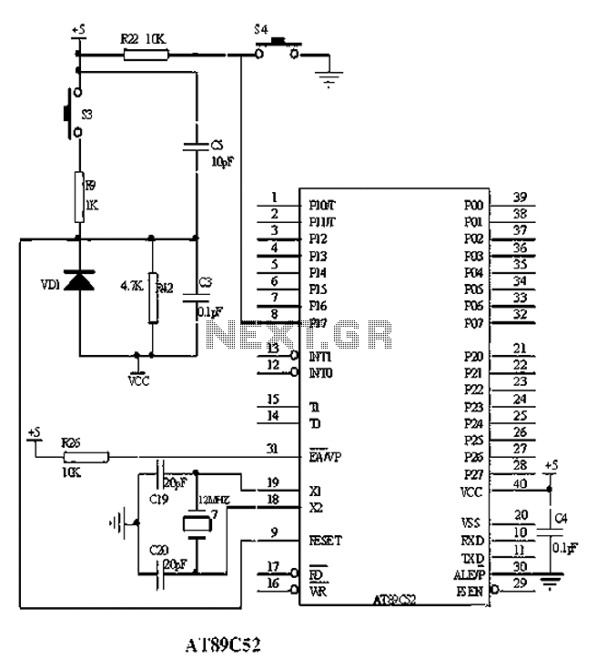
The American Atmel AT89C52 is a low-voltage, high-performance CMOS 8-bit microcontroller chip that contains 8KB of rewritable program memory and 256B of random access data memory (RAM). Atmel's high-density devices utilize non-volatile memory technology and are compatible with the...
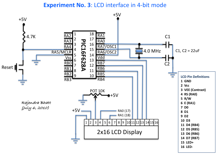
An HD44780 Character LCD is a liquid crystal display (LCD) device designed for interfacing with embedded systems. These screens are available in various configurations, including 8x1 (one row of eight characters), 16x2, and 20x4. The most commonly produced configuration...

Low line current loading is provided by the H11BX522 photodarlington optocoupler, which delivers a 1 mA output from a 0.5 mA input. The H11BX522 is a photodarlington optocoupler that is designed to provide electrical isolation between its input and output...
This design was developed to create a highly stable reference locked to a 10MHz source. With minor hardware modifications and entirely new firmware, an excellent GPS Disciplined Oscillator (GPSDO) was achieved using the same circuit board. The design effectively...
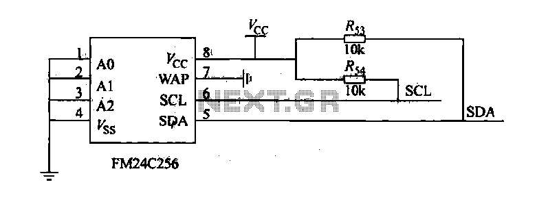
The FM24C256 is utilized as a slave interface circuit in an I2C bus configuration, with the address format specified in Table 27-3. The address pins A2, A1, and A0 are set to low; however, for extended storage capacity, adjustments...