
50MHz Linear Power Amplifier


The construction is straightforward. The input power to the PA comes from a 50MHz transmitter built in previous projects, delivering about 10-20mW into 50 ohms. At the bottom of this page, a complete schematic for a transmitter that will deliver about 100mW will be provided. The transmitter heart from previous projects is recognizable, featuring a crystal-controlled VCO.
This PA operates in class C, meaning it functions for less than half of the input cycle. Its efficiency is about 75% since the active device is biased beyond cutoff. Class C amplifiers are commonly used in RF circuits, where a resonant circuit must be placed at the output to sustain the sine wave during the non-conducting portion of the input cycle. The input power to this device should be around 10-20mW or (+10 to +13dBm). A DC current flows through the emitter, with resistor R1 setting the power gain and the DC current. A resistor value that is too low will result in excessive current, potentially damaging the transistor. A suitable value for R1 is found to be between 5-10 ohms.
The output consists of a 3-pole filter designed to match 50 ohms. Capacitors C1, C2, and inductor L2 have specific values that achieve this match. It is recommended to replace C1 and C2 with variable capacitors or to add a capacitor in parallel with a regular capacitor for fine-tuning the output for optimal performance. A combination of a 150pF capacitor in parallel with an 80pF variable capacitor is suggested. The antenna should be a 50-ohm type, with a 1/4 wavelength whip antenna being ideal. Frequency adjustments can be made in increments of 10 kHz. C1 and L2 form a resonant circuit that should resonate at 50MHz. L3, along with 10pF and 6.8pF capacitors, is also tuned to 50MHz. This filter cleans up the signal before it reaches the FET BF245B.
The FET functions as a follower; it does not amplify but increases current. A modification has been made by replacing the source resistor with a coil, which has been found to yield more power than a 1k resistor. Adjustments can be made to find the optimal output power. The next stage is a booster, with resistor R2 setting the current and gain of this booster. A low resistor value may increase the current excessively, risking damage to the transistor. Typical values for R2 range from 20-100 ohms. However, a drawback is that current consumption will increase, resulting in faster battery depletion. The current consumption in the emitter does not directly correlate with output power.
To measure output power, connect a 50-ohm resistor in series with a 10nF capacitor, connecting the capacitor to the collector and the resistor to ground. The final stage should not be connected yet. Output power can then be measured across the 50-ohm resistor using an oscilloscope, while adjusting R2 and tuning C1 and L3 for optimal output power. Measurements indicate approximately 17mW output into 50 ohms with a 9V DC supply in this specific construction. The choice of 9V is based on battery usage, with this PA capable of delivering over 100mW output power. The current consumption typically ranges from 150-200mA, and the transistor does not overheat. Increasing power output is possible, necessitating an increase in R1 (maintaining current around 150mA) for greater power from this PA.This page investigates a simple PA for 50MHz. This power amplifier will boost upp a low level signal about10-20mW to over 100mW. The power consumption will yet be quit low. At the bottom of this page I will present a complete transmitter based on a crystal controlled VCO. This PA is based on a common cheap power transistorBFG97. I use this transistor in my previous transmitter projects. This PA work in class C and will deliver about 100mW. The current consumption is about 100-150mA at 9V. Why I have choosen 9V as power supply is because I will in most cases use my transmitter with a common 9V battery. If you use higher voltage you will increase the output power. I don't want to consume all to much energy from the battery, so I have settled with 100mW output power.
The construction is very easy. The input power to my PA comes from a 50MHz transmitter I have built in previous projects. The transmitter I used delivered about 10-20mW into 50 ohm. At the bottom of this page I will present a complete shematic for a transmitter that will deliver about 100mW. I guess you will recognize the transmitter hart from my previous projects, I just love this crystal controlled VCO.
Now, let's take a look at this schematic. This PA works in class C. Class C amplifiers operates for less than the half input cycle . It's efficiency is about 75% because the active device is biased beyond cutoff. It is commonly used in RF circuits where a resonant circuit must be placed at the output in order to keep the sine wave going during the non-conducting portion on fthe input cycle. The input power to this device should be around 10-20mW or (+10 to +13dBm). There will be a DC current going through the emitter. Resistor R1 set the power gain and the DC current. A to low resistor value will make the current to high and you will burn your transistor. I found that 5-10 ohm is a suitable value. The output consist of a 3-pole filter designed to 50 ohm match. C1, C2 and L2 has given the exact values. I would recomend you to replace C1 and C2 with a variable capacitor (or add a capacitor parallel to a regular capacitor) then you can fine tune the output for best performance.
A 150pF capacitor parallel with a 80 pF variable capacitor will do good. The antenna should be 50ohm type, wich means a 1/4 wave lenght whip antenna will be perfect. You can change the frequency by some 10:th of kiloherts. C1 and L2 is a resonans circuit and should be in resonans at 50MHz. L3 and the 10pF and the 6.8 pF capacitors is also tuned to 50MHz. This filter cleans up the signal before it goes to the FET BF245B. The FET is working as a follower, it doesn't amplify, it just boost up the current. I have made a slightly changes by replacing the source resistor with a coil. I noticed that I could get more power out of this FET with a coil than a 1k resistor. You can play a bit yourself to find the best output power. Next stage is a booster. The reisistor R2 set the current and the gain of this booster. A to low value will increase the current and you might end up blowing the transistor. I usually use 20-100ohm. A dissadvantage is that the current consumption will increase and if you are using battery it will be empty faster. The current consumption in the emitter is not proportion the output power. Connect a 50ohm resisitor in serie with a 10nF capacitor and connect the capacitor to the colector and the resistor to ground.
Don't connect the last stage yet. Now you can measure the output power over the 50 ohm resistor. I use an oscilloscope and then I play with the value of R2 and I also tune C1 and L3 for best output power. In my measurement I come up to about 17mW into 50 ohm with 9V DC in this exactly construction. I have choosen the voltage to 9V because I use a battery and this little PA will give you more than 100mW output power.
The current consumption is about 150-200mA. The transistor didn't get hot at all. You could increase the power and you must then increase R1 as well (keep the current around 150mA) and you will get even more power from this PA. 🔗 External reference
Related Circuits
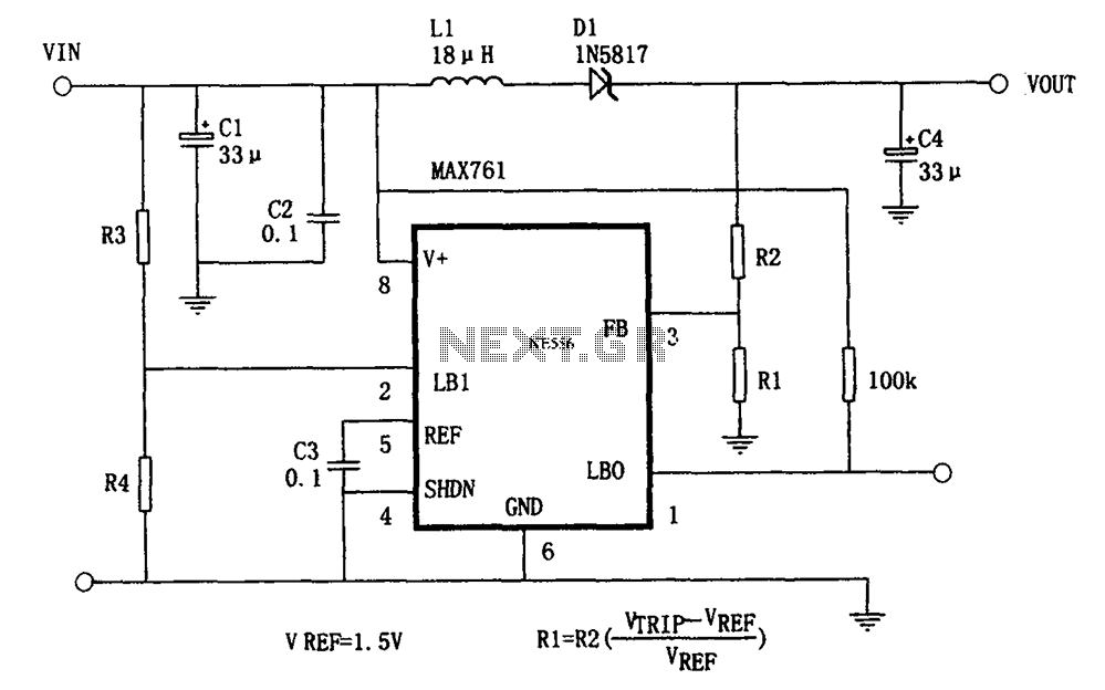
The circuit features an efficient, low-power output voltage boost DC-DC converter, MAX761, along with a few external components that facilitate adjustable power conversion. The output voltage is determined by the ratio of resistors R1 and R2, calculated using the...
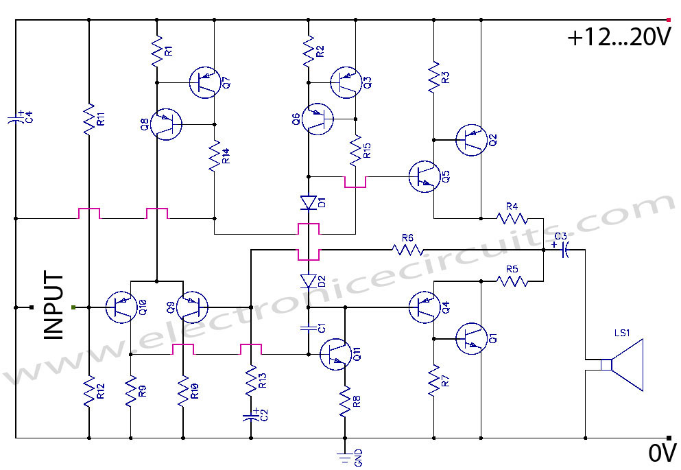
Discrete Class AB Transistor Audio Power Amplifier Circuit Diagram. This is a Class AB transistor power amplifier. It is a simple amplifier to... A Class AB transistor audio power amplifier is designed to provide high-quality amplification for audio signals while...
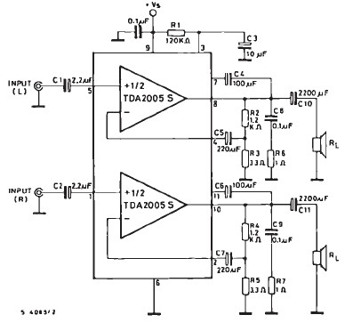
The TDA2005 car audio amplifier circuit is specifically designed for use in devices such as car radios, CD players, and similar equipment. This amplifier is based on the TDA2005 audio integrated circuit (IC), capable of delivering a maximum output...
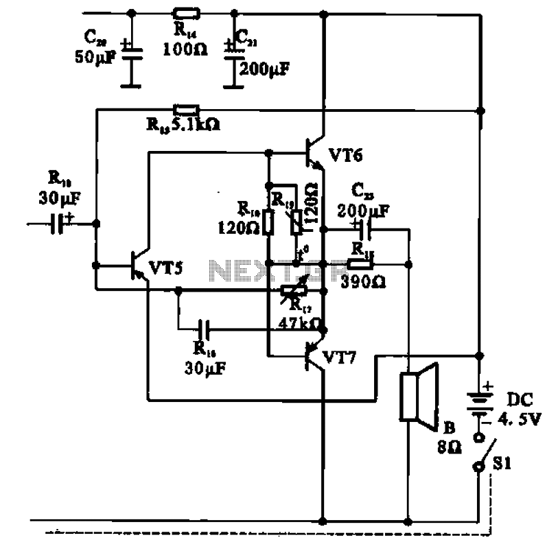
The transistor radio features a common output transformerless (OTL) power amplifier circuit. The VT5 component serves as the bias resistor for the driver stage. VT6 and VT7 form a complementary symmetry configuration, with VT6 being a germanium NPN transistor...
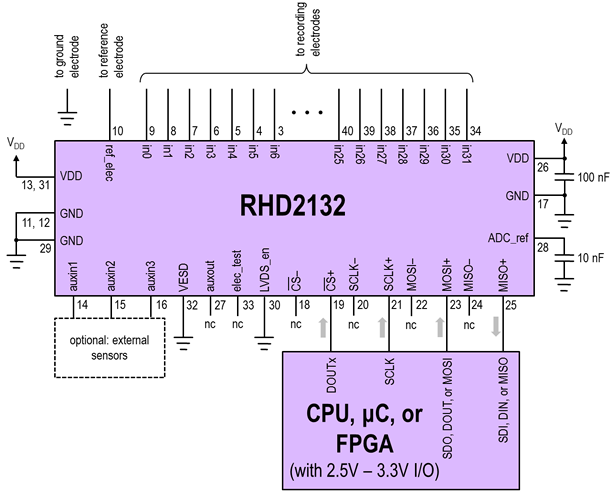
The Intan Technologies RHA2116 is a 16-channel integrated amplifier array that requires only three external resistors to set the amplifier bandwidth, two capacitors for power supply smoothing, and occupies one square centimeter of board area. The digital-output and analog-output...
When a short circuit to ground occurs, causing a DC voltage across the loudspeaker to be greater than or equal to V, an integrated protection circuit activates. This circuit limits the DC voltage across the loudspeaker to a value...