
Common series negative feedback amplifier

The common series negative feedback amplifier operates by utilizing a negative feedback loop to enhance stability and control over the gain of the amplifier. The resistor R, positioned in the feedback path, plays a crucial role in determining the overall gain of the circuit. By introducing feedback, the amplifier can correct for variations in input signal levels, ensuring a more consistent output.
When a positive input signal is applied, the transistor's emitter voltage rises, reflecting the input voltage. This relationship is critical for understanding how the amplifier processes signals. The feedback resistor R diminishes the input signal, effectively lowering the voltage at the base-emitter junction to Ube. The negative feedback introduced by R counteracts any fluctuations in input signal, stabilizing the amplifier's performance.
Furthermore, the coupling capacitor C facilitates AC signals by bypassing the negative feedback for alternating current. This configuration allows AC signals to pass through without the influence of the feedback loop, enabling the amplifier to achieve a higher gain for AC applications while maintaining stability for DC signals.
In summary, the common series negative feedback amplifier is a versatile circuit that utilizes negative feedback and coupling capacitors to optimize performance across different signal types. The careful selection of resistor R and capacitor C values is essential for achieving the desired amplification characteristics while ensuring stability and reliability in the amplifier's operation. Common series negative feedback amplifier (2) series negative feedback amplifier shown in series is a common negative feedback amplifier. Wherein R is the resistor current nega tive feedback element, because it belongs to the input circuit, output circuit belongs to the input and output circuit linked up. First, assume that an instantaneous input signal is positive (+), due to the emitter (e) of the polarity of the voltage to the base (b) the same, but also for the positive (+), increases the potential of the transistor emitter.
Because the emitter voltage is equal to the input voltage Ub {-U-Uf, through feedback element R, weaken the input signal into a voltage Ube, so negative feedback is feedback elements R. A negative feedback resistor R is used to stabilize the amplifier, the greater the resistance, the entire amplifier is smaller magnification.
And a negative feedback resistor R is connected in parallel to a capacitor coupling capacitor C, corresponds to the AC emitter (e) of the short-circuit, the AC signal has no negative feedback, thereby to obtain a larger magnification AC
Related Circuits
Feedback in a public address amplifier should be avoided. The ideal solution is to adjust the positions of the microphone and speaker; however, this is not always feasible in many situations. A frequency shifter that alters the output frequency...
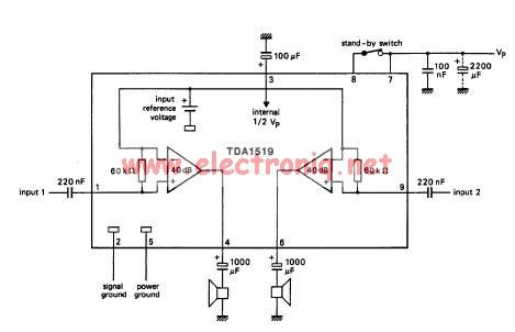
The TDA1519 circuit can deliver 2x6 watts of output power. The TDA1519 is an integrated class-B dual output amplifier housed in a 9-lead single in-line (SIL) plastic medium power package, primarily developed for car radio applications. The TDA1519 amplifier is...
The 10-meter 27MHz continuous wave (CW) radio amplifier is equipped with the VN66AF transistor produced by Siliconix, which offers several advantages: it is inexpensive, provides excellent dielectric insulation, and has high gain. The VN66AF is utilized as an RF...
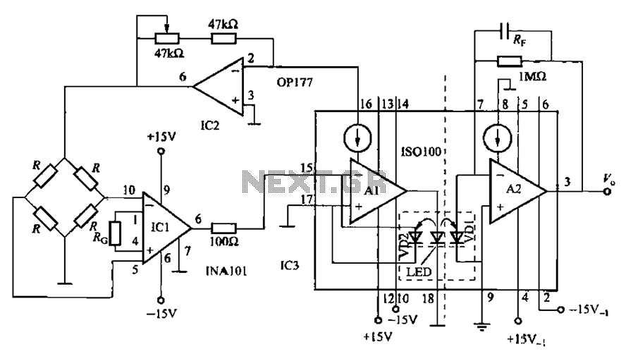
A bridge sensor output signal precision differential instrumentation amplifier with adjustable gain IC1 amplified signal IS0100. The gain of IC1 is determined by the external resistor Rc. The IC2 current source output is sent to drive the bridge sensor,...
Headphone listening can be technically superior as it eliminates room reflections and provides intimate contact between the transducer and the ear. Headphones are designed to deliver sound directly to the ears, thereby minimizing the influence of the surrounding environment. This...
This wideband DTV UHF antenna TV amplifier provides a total gain ranging from 10 to 15 dB within the frequency domain of 400 to 850 MHz. The wideband DTV UHF antenna TV amplifier is designed to enhance signal strength for...