
27MHz CB Amplifier Circuit

The 10-meter 27MHz CW radio amplifier circuit utilizes the VN66AF transistor, which is a vertical N-channel MOSFET designed for efficient RF applications. The transistor's high gain characteristics make it suitable for amplifying weak radio signals in the 26-30 MHz frequency range, which is critical for effective communication in amateur radio.
The circuit design incorporates a biasing network to ensure the VN66AF operates in its optimal region, allowing for linear amplification when required. For applications involving AM and SSB, the gate current must be precisely set to 20mA. This is achieved through the adjustment of potentiometer P1, which allows for fine-tuning of the gate voltage, ensuring the transistor remains in the active region for linear amplification.
When configuring the amplifier for FM and CW modes, it is essential to adjust P1 to eliminate any gate current. This adjustment is crucial as it prevents distortion and ensures that the amplifier operates efficiently in these modes. The steady-state current, which is the current flowing through the transistor when it is in operation, is maintained between 200mA and 300mA. This range is critical for achieving the desired output power while preventing overheating and ensuring reliability.
The circuit should also include appropriate bypass capacitors to filter out noise and stabilize the power supply. Additionally, an output matching network may be necessary to ensure maximum power transfer to the antenna, optimizing the amplifier's performance. Proper heat sinking should be employed to dissipate heat generated by the VN66AF during operation, safeguarding the transistor from thermal damage.
In summary, the 10-meter 27MHz CW radio amplifier utilizing the VN66AF transistor is an effective solution for amateur radio applications, offering flexibility for various modulation types while ensuring reliable performance through careful biasing and current management.The 10 meters 27MHz CW radio amplifier is equiped with VN66AF transistor produced by Siliconix wich has some advantages: its cheap, great dielectric insulation and high gain. Here we use VN66AF as an rf amplifier for 10m band (26 30 MHz ). For linear applications (AM and BLU) the VMOS FET gate current has to be 20mA adjusted with P1. If we wan t to use this 10m rf amplifier for FM and CW adjust P1 so there is no current to FET gate. In our case the repose current ( steady current ) is 200mA to 300mA. 🔗 External reference
Related Circuits
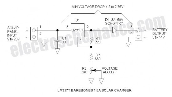
This is the simplest and most affordable solar battery charger that a hobbyist can create. It has some drawbacks compared to other similar controls, but offers unique advantages. The solar battery charger circuit is designed to harness solar energy to...
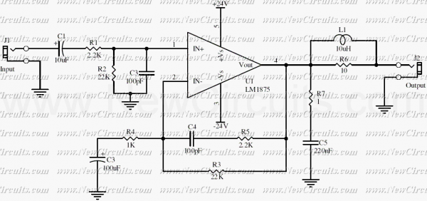
This simple 20 watts audio power amplifier is designed for home-brewed purpose. The L1 should be able to handle a current up to 4A to drive speaker in full load. The distortion is 0.015% @ 1KHz / 20W. This...
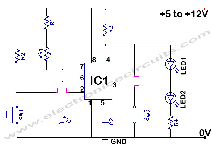
The 555 Timer Time Delay Circuit uses LEDs to visually indicate the status of the circuit at any moment. The operation begins when the reset switch, SW2, is activated. The 555 Timer is a versatile integrated circuit widely used for...
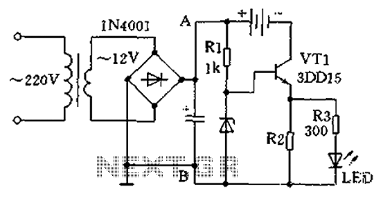
A practical single-tube constant current charger is illustrated, utilizing a transistor (VT1) that plays a crucial role in maintaining a constant current. The current value is determined by the voltage regulator and resistor R2. The general output voltage is...
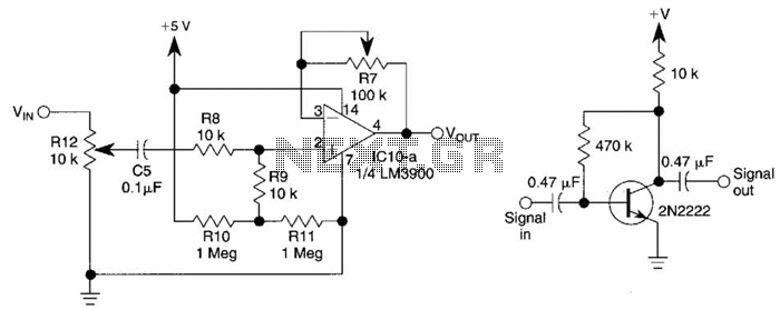
This circuit utilizes one-quarter of an LM3900 to create a simple variable-gain front end for an oscilloscope. R7 serves as the gain control. Additionally, a basic preamplifier is included for applications requiring more than 10X gain. The circuit employs the...
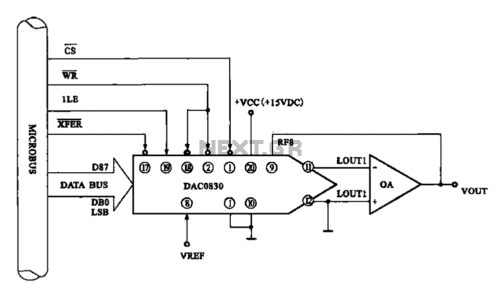
Figure 8 illustrates a typical digital-to-analog (D/A) conversion circuit that utilizes the DAC0830/DAC0832 chip. The microprocessor outputs an 8-bit digital signal, which is converted into an analog signal. The D/A conversion circuit depicted employs the DAC0830/DAC0832, which is a dual...