
communicate with the picaxe

The RS232 communication setup for PICAXE microcontrollers is essential for enabling serial data transmission between the PICAXE and a PC or other serial devices. This tutorial provides a comprehensive approach to establishing RS232 communication, covering the necessary components, circuit design, and software configuration.
The circuit diagram typically includes a PICAXE microcontroller, a MAX232 level converter, and the necessary capacitors to ensure proper voltage level shifting between the microcontroller and RS232 standard levels. The MAX232 is crucial as it converts the TTL signal levels from the PICAXE to the higher voltage levels required by RS232 devices, and vice versa.
For the serial cable configuration, a standard DB9 connector is commonly employed. The wiring should connect the relevant pins from the DB9 to the MAX232, ensuring that the Tx (transmit) and Rx (receive) lines are correctly aligned. The typical configuration involves connecting the PICAXE’s Tx pin to the MAX232’s Tx output and the Rx pin to the MAX232’s Rx input.
In terms of software setup, a PC communication program such as PuTTY or Tera Term can be utilized to establish a serial connection. The configuration settings typically include selecting the correct COM port, setting the baud rate (commonly set to 4800 or 9600 bps), and ensuring the data bits, stop bits, and parity settings match those configured in the PICAXE program.
Sample code for the PICAXE is essential for testing the communication link. The code should include commands for sending and receiving data via the serial interface, demonstrating how to transmit simple messages or variable data from the PICAXE to the PC. This code serves as a practical example of how to utilize the established RS232 communication link effectively.
Overall, this tutorial provides a foundational understanding of setting up RS232 communication with PICAXE, detailing the hardware connections, software configurations, and example code necessary for successful implementation.A tutorial on setting up RS232 communication to PICAXE with circuit diagram, serial cable configuration, PC communication program setup and configuration and sample code for PICAXE.. 🔗 External reference
Related Circuits
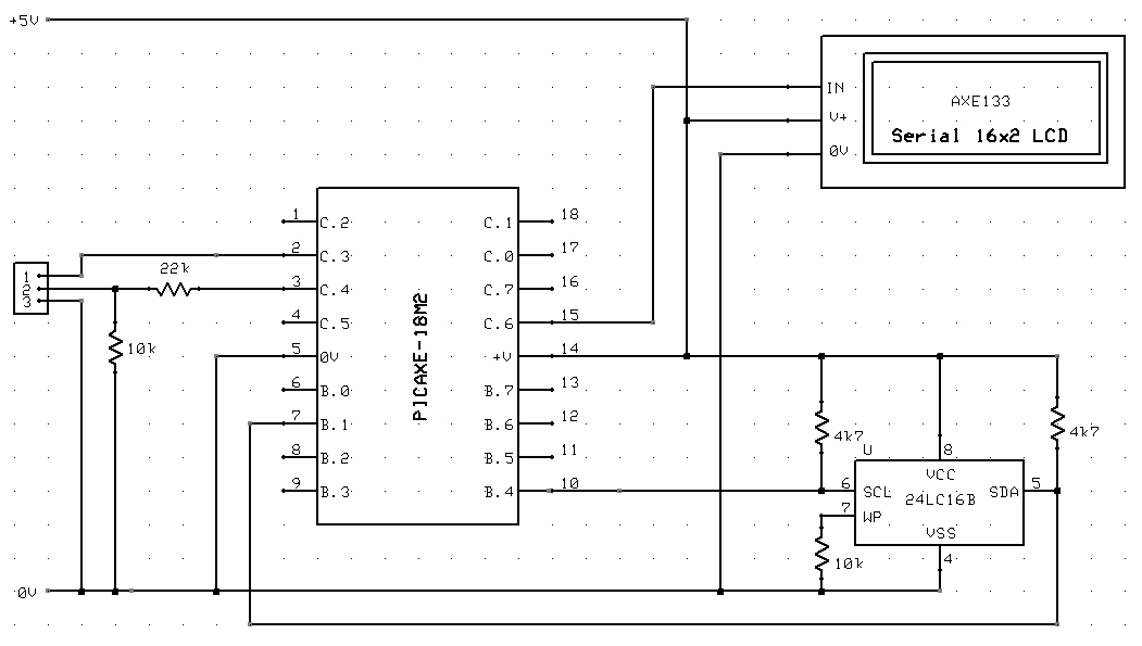
A circuit diagram and sample code is provided to read and write to the 74LC16B memory from a PICAXE microcontroller. The circuit involves interfacing a PICAXE microcontroller with a 74LC16B memory chip, which is a type of EEPROM (Electrically Erasable...
This circuit addresses the challenge of transmitting data over a cable that lacks available conductors. The data is modulated using On-Off Keying (OOK) and superimposed on a high-frequency carrier, allowing it to be transmitted over a low-voltage power supply...
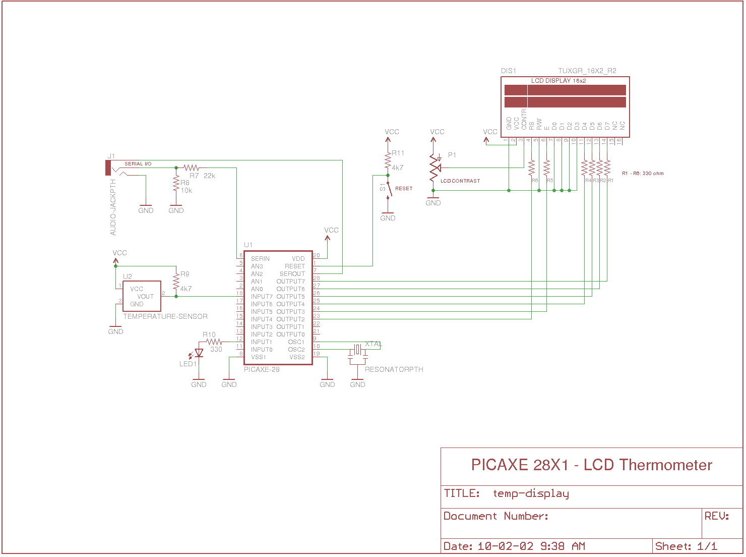
Measures the temperature using the DS18B20 temperature sensor, displays the reading on a 2x16 character LCD, sends the data to a serial terminal, and checks the temperature against predefined limits. The output is set high if the temperature is...
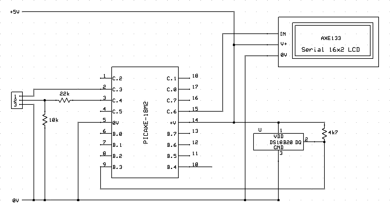
A circuit diagram and example code to implement and use the DS18B20 temperature sensor in PICAXE, both in rounded and full 12-bit resolution. The DS18B20 is a digital temperature sensor that communicates over a 1-Wire interface, allowing multiple sensors to...
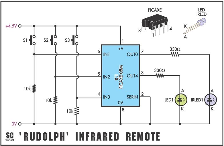
To send the Sony command "TV - mute," the command would be infraout 1, 20. Note that the device should always be 1 when used in PICAXE projects, and data can only be between 0 and 127, as the...
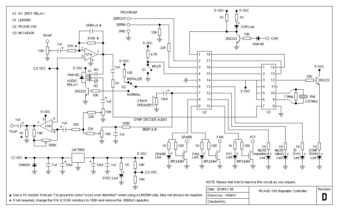
The project involves testing the capabilities of a PICAXE-18X chip operating at 4 MHz for a specific application. It includes designing the circuit, creating printed circuit board (PCB) artwork, etching the PCB, programming the PICAXE in BASIC, and connecting...