
read and write to 74lc16b memory in picaxe

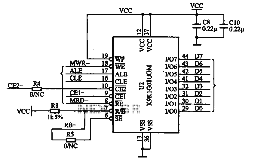
The circuit involves interfacing a PICAXE microcontroller with a 74LC16B memory chip, which is a type of EEPROM (Electrically Erasable Programmable Read-Only Memory). The PICAXE microcontroller serves as the control unit, executing instructions that allow for data manipulation within the memory chip.
In the schematic, the PICAXE microcontroller is connected to the 74LC16B via a series of data and control lines. The data lines are typically connected to the microcontroller's digital output pins, which will send and receive data to and from the memory. Control lines such as Chip Select (CS), Write Enable (WE), and Output Enable (OE) are also connected to specific pins on the microcontroller to manage the read and write operations effectively.
The circuit is powered by a suitable voltage source, often 5V, which is common for both the PICAXE and the 74LC16B. Pull-up resistors may be used on the data lines to ensure stable logic levels during operation.
The sample code provided is essential for understanding how to implement the read and write functions programmatically. It typically includes initialization routines for setting up the memory interface, functions for writing data to specific addresses, and functions for reading data back from those addresses.
Overall, this circuit serves as a practical example of how to interface a microcontroller with an external memory device, showcasing fundamental principles of digital electronics and embedded systems programming.A circuit diagram and sample code is provided to read and write to 74LC16B memory from a PICAXE microcontroller.. 🔗 External reference
Related Circuits
This circuit provides a visual 9-second delay using a 7-segment digital readout LED. When the switch is closed, the CD4010 up/down counter is preset to 9, and the 555 timer is disabled, holding the output high. When the switch...
This document illustrates the application of the MP3 player memory chip ACU7505 within a clamor circuit, designed to support the overall machine CPU and MP3 decoder core. The chip is utilized to address high data storage capacity requirements, implemented...
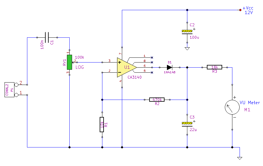
This simple circuit, designed with a minimal component count, indicates peak audio response on an analog meter, similar to a tape recorder's meter. It employs an operational amplifier configured as a non-inverting amplifier, with the addition of a diode...
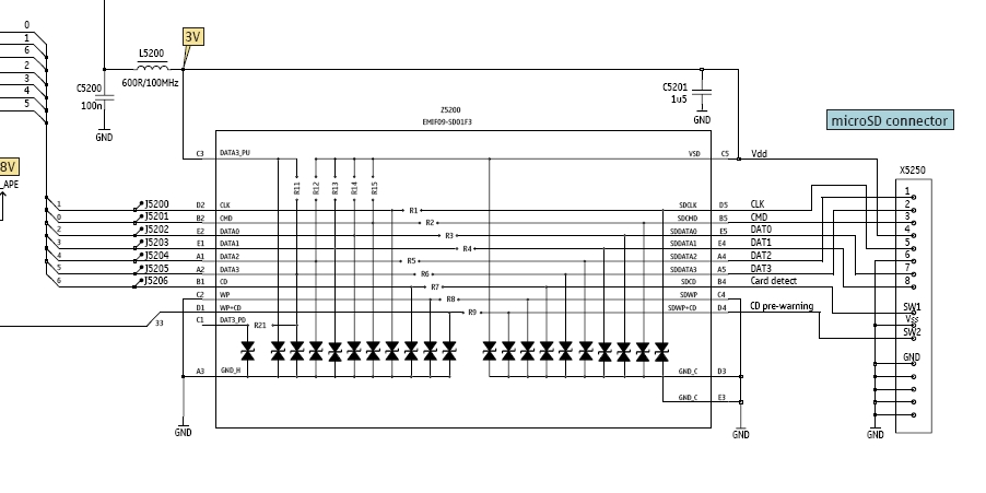
In this tutorial, the functioning of the memory card circuit in mobile phones will be explored. The previous post discussed the pin-outs and types of memory cards utilized in cellular devices. The accompanying block diagram illustrates how the removable...
RFID technology is highly versatile, has numerous applications, and has become affordable and easy to implement in recent times. This tutorial outlines the process of interfacing an RFID Reader with a standard Atmel AVR microcontroller. RFID (Radio Frequency Identification) systems...
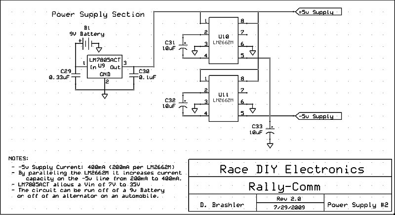
This circuit utilizes the LM2662M integrated circuit from National Semiconductor, which serves as a direct replacement for the MAX1044 but in a smaller surface mount package. Additionally, the main voltage regulator has been upgraded to the LM7805ACT. This circuit...