
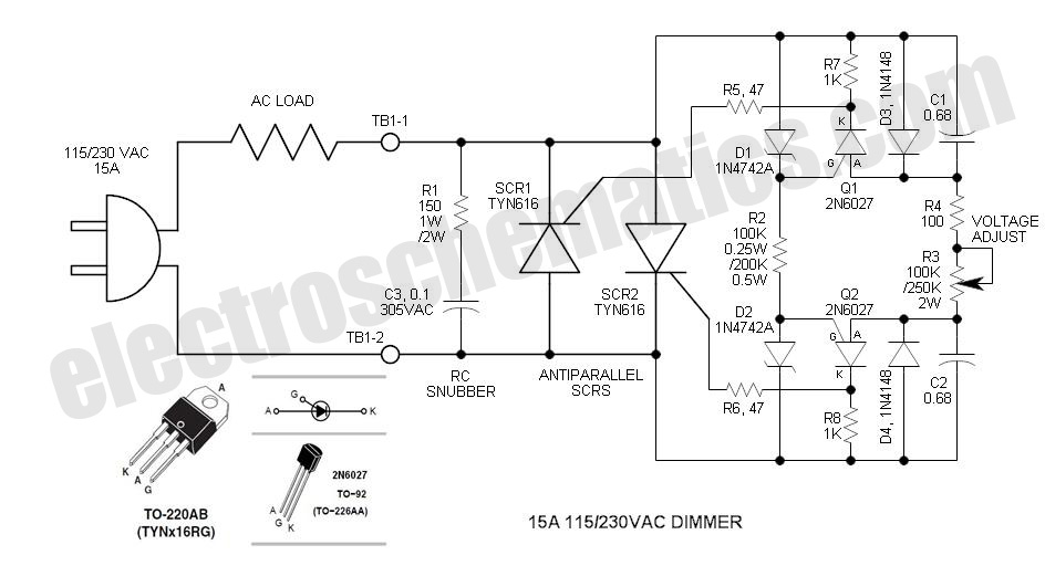
Complementary lighting control

This lighting control circuit is designed to manage the brightness of two lamps in a complementary manner, ensuring a smooth transition between the two light sources. The operation is based on the principle of phase control, where the conduction angle of SCR1 is varied to achieve the desired brightness level for lamp L1. When SCR1 is off, a small portion of the current is allowed to flow through the components D1 and R1, which is crucial for the triggering of SCR2. This ensures that SCR2 remains in the off state until SCR1 is activated.
The inclusion of capacitor C1 plays a vital role in the operation of the circuit. When SCR1 is turned on, it interrupts the current flow, which leads to the rapid discharge of C1. This discharge generates a negative voltage spike that effectively turns off SCR2, ensuring that the second lamp's brightness decreases as the first lamp's brightness increases. The design allows for a seamless transition between the two lamps, creating an aesthetically pleasing lighting effect that can be utilized in various applications, such as stage lighting, mood lighting in homes, or in theatrical productions.
The use of a unijunction transistor or diac for phase control provides a reliable method for adjusting the gate voltage of SCR1, allowing for precise control over the timing of the SCR's conduction. This enables the circuit to maintain synchronization between the two lamps without the need for additional adjustments, making it user-friendly and efficient. Overall, the lighting control unit exemplifies a sophisticated approach to managing dual lamp brightness in a coordinated manner.This lighting-control unit will fade out one lamp while simultaneously increasing the light output of another. The two loads track each other accurately without adjustments. The gate of SCRl, a silicon-controlied rectifier, is driven from a standard phase-control circuit, based, for example, on a unijunction transistor or a diac.
It controls the brightness of lamp LI directly Whenever SCRl is not on, a small current flows through LI, Dl, and Rl, permitting SCR2 to fire. When SCRl turns on, current flow ceases through Dl and Rl; the energy stored in Cl produces a negative spike that turns SCR2 off.
Related Circuits
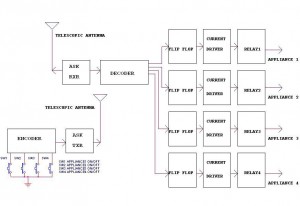
This circuit illustrates a remote control circuit diagram using RF technology without the use of a microcontroller. Features include a simple remote control circuit that operates via radio frequency. The remote control circuit operates by transmitting signals through radio waves,...
This is an enhanced infrared (IR) remote control extender circuit. It features high noise immunity, resistance to ambient and reflected light, and an increased operational range. The improved IR remote control extender circuit is designed to extend the range of...
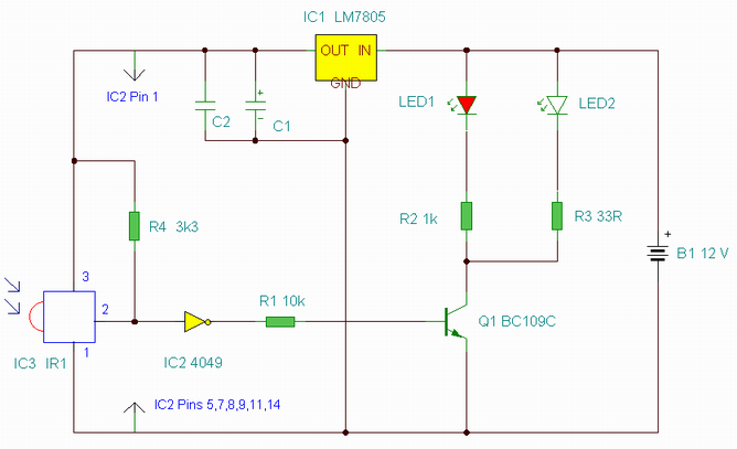
The DIAC is a 28V bidirectional trigger device commonly used in inexpensive phase control applications. Its trigger voltage is relatively high for 115VAC phase control. In the past, a similar low voltage trigger device known as a Shockley diode...
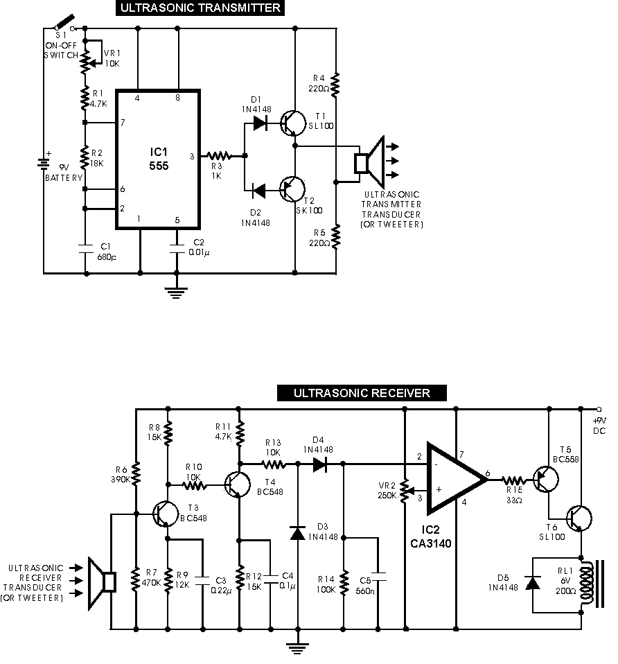
Circuit of a new type of remote control switch is described here. This circuit functions with inaudible (ultrasonic) sound. Sound of frequency up to 20 kHz is audible to human beings. The sound of frequency above 20 kHz is...
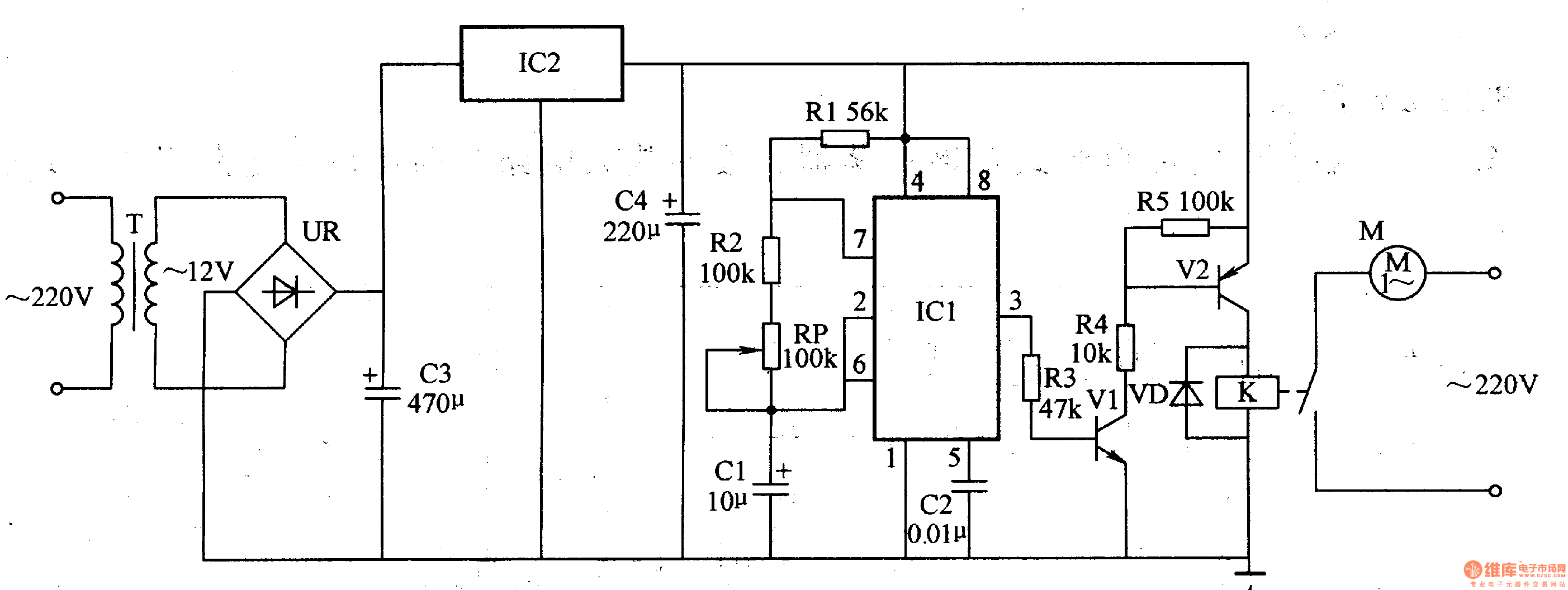
The medical ventilator controller circuit consists of an astable oscillator, a control circuit, and a power supply circuit. The astable oscillator is constructed using resistors R1, R2, a potentiometer RP, capacitors C1, C2, and a time base integrated circuit...
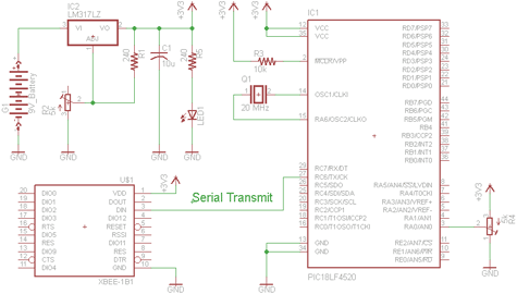
There are two schematics to examine for constructing a transmitter/receiver system. The first schematic is the transmitter, featuring a variable trimpot connected to RA0. The trimpot's value will be transmitted from the Tx pin of the PIC to the...