
Xbee Wireless Servo Motor Control Circuit

The transmitter circuit consists of a PIC microcontroller that utilizes a trimpot to provide an adjustable voltage input to its analog-to-digital (A/D) converter on pin RA0. The trimpot is configured such that its outer pins are connected to the power supply and ground, while the central pin outputs a variable voltage based on the trimpot's position. The A/D converter digitizes this voltage into an integer value ranging from 0 to 50. This digitized value is then transmitted via the PIC's UART (Universal Asynchronous Receiver-Transmitter) at a baud rate of 9600 BPS to the Din pin of the Xbee module, which is responsible for wireless communication.
On the receiving end, the Xbee module captures the transmitted data through its Dout pin, which is directly connected to the Rx pin of another PIC microcontroller. The receiving PIC decodes the incoming serial data and translates it into movement coordinates for a servo motor. The integer value received is utilized to adjust the PWM signal that controls the position of the servo motor, enabling precise movement based on the input from the trimpot.
The design allows for seamless communication between the transmitter and receiver using Xbee modules, which are known for their robust wireless capabilities. The automatic connection feature of the Xbee ensures that once powered on, the receiver will initiate communication with the transmitter without requiring additional configuration. This setup is ideal for applications requiring remote control of servo motors based on variable input signals.There are two schematics that we`ll look at to see how to build this transmitter/receiver system. The first one is the transmitter, with a variable trimpot input into RA0. The trimpot value will be sent out of the Tx pin of the PIC and to the Din pin of the Xbee module to send the signal wirelessly. The receiver circuit, will receieve the transmitted signal through the Xbee module, out of the Dout pin and to the PIC`s Rx pin. The receiving PIC will then translate the data to movement coordinates for the servo motor. The input we will give to the PIC`s will come from a standard trimpot`s output. The trimpot is tied to power and ground, with the middle pin being a variable voltage send to the PIC`s A/D converter on pin RA0. The PIC will then translate this input to an integer of value 0-50 and send it via the PIC`s serial communication module at 9600 BPS to the Xbee`s Din pin.
After the serial data is receieved by the PIC, it will put the dynamic integer value into the the delay cycle that is creating a PWM output to control the servo motor. Each specific value of 0 to 50 correlates to a specific location that the motor can move to. The Xbee receiver will automatically connect with the transmitter and begin receiving data. All data will be receiving and output via the Dout pin on the Xbee module. The Dout pin is conneceted directly to the PIC`s Rx pin so that the PIC can catch the data. 🔗 External reference
Related Circuits
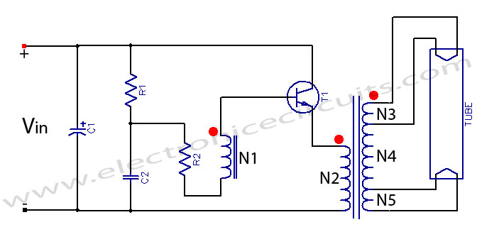
Fluorescent tube light circuit of an inverter that uses a single transistor and a single transformer. This type of inverter can be made in various configurations. The fluorescent tube light circuit described utilizes a basic inverter design that incorporates a...
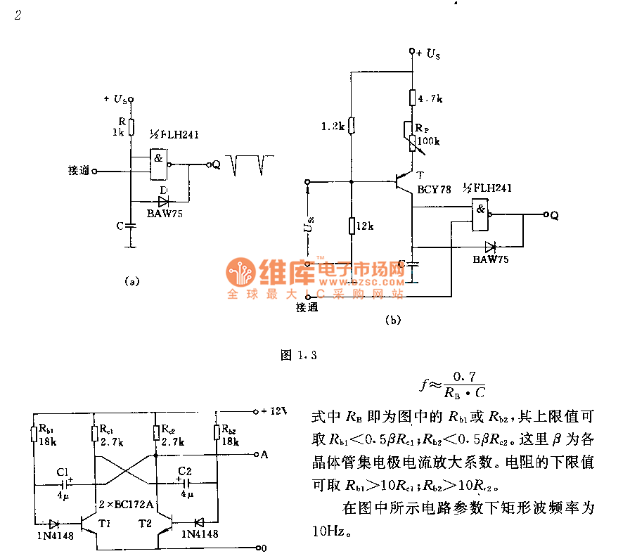
The circuit consists of two components whose parameters and models are designed to simultaneously generate a rectangular wave with a duty cycle of 1:1. The frequency is defined by the equation f = 0.7/(RB * C), where RB refers...

400 W MOSFET Audio Amplifier circuit using IRFP448. This circuit is categorized under amplifiers and includes five circuit diagrams. For more detailed information, refer to the main post titled "400 W MOSFET Audio Amplifier Using IRFP448." This post also...
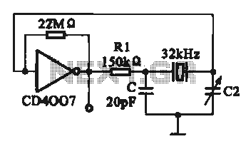
A 32 kHz clock oscillator is essential for digital circuits, as depicted in the schematic. The 32 kHz crystal clock oscillator serves to provide a time reference signal for the digital circuit. It utilizes a CMOS integrated circuit, specifically...
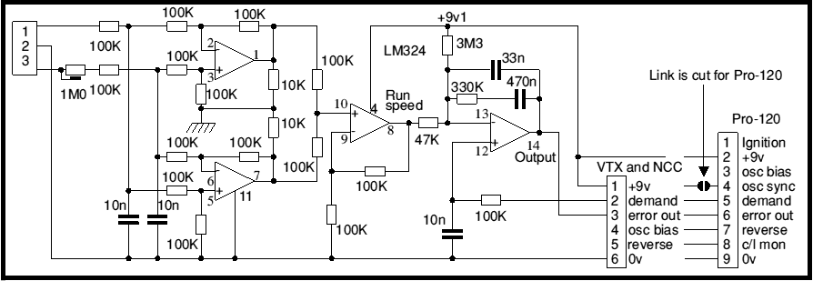
Most battery motor speed controllers are under manual control and the operator automatically adjusts speed to match demand. Under these conditions closed loop motor speed control is an unnecessary expense. However, when it is required, a tachogenerator can easily...
A simple 3-way crossover, intended for triamping Hi-Fi systems. This is a conventional 12dB / Octave unit, and cannot be expected to have the same performance as a Linkwitz-Riley aligned filter network. It will still be a vast improvement...