
COMPLETE 2 W SERVO AMPLIFIER

The described circuit utilizes a direct-coupled preamplifier design which allows for improved frequency response and lower distortion by eliminating coupling capacitors. This configuration enhances the performance of the amplifier by maintaining a consistent bias point, which is critical for linear amplification.
The substantial d-c feedback employed in the circuit serves to stabilize the operating point against variations in temperature and component tolerances. This feedback mechanism contributes to maintaining the desired voltage gain while reducing distortion and improving linearity.
With a voltage gain of 10,000, the amplifier is capable of significantly amplifying low-level signals. This high gain is essential in applications where weak signals need to be processed, such as in audio or sensor applications. The closed feedback loop ensures that the gain remains stable and predictable under varying load conditions.
The overall efficiency of 50% indicates that half of the power supplied to the circuit is effectively utilized for signal amplification, while the remaining power is dissipated as heat. This efficiency level is typical for linear amplifiers, where power consumption is a critical design consideration.
The input impedance of 10,000 ohms is advantageous for interfacing with high-impedance sources, minimizing the loading effect on the signal source and allowing for better signal integrity. Conversely, the output impedance of 150 ohms is well-suited for driving low-impedance loads, ensuring effective power transfer and compatibility with subsequent stages in the signal chain.
In summary, this circuit design exemplifies a robust approach to signal amplification, combining high gain, stability, and efficient operation, making it suitable for various electronic applications requiring precise signal processing.Includes direct-coupled preamplifier and driver stages, with considerable d-c feedback to stabilize bias conditions. Voltage gain of amplifier with feedback loop closed is 10, 000. Overall efficiency is 50%. Input impedance is 10, 000 ohms and output impedance is 150 ohms. -Texas Instruments Inc. , "Transistor Circuit Design, " McGraw-Hill, N. Y. , 1963, p 247. 🔗 External reference
Related Circuits
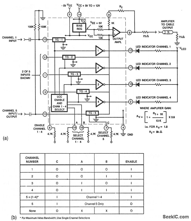
This circuit illustrates a CA3256 switch/amplifier configured for a direct-coupled output. One of four channels can be selected in parallel with channel 5. The analog switches of channels 1 to 4 are digitally controlled by logic. A VEE of...
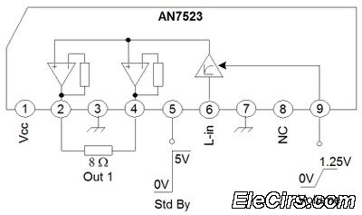
The third series of the function utilizes the same system, specifically BTL (Bridge Transformer Less). This configuration offers several advantages, including the elimination of coupling capacitors and coupling transformers. The BTL (Bridge Transformer Less) configuration is a significant advancement in...
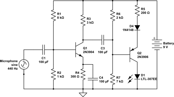
The circuit takes input from a microphone to power an LED, which remains off in ambient sound conditions and brightens with increasing noise levels. The peak voltage produced by the microphone is proportional to the sound levels. The microphone...
This is a convenient and straightforward general-purpose 50-watt amplifier. The amplifier features an input for connecting devices such as radios, TVs, or stereo equipment. Additionally, it includes a phono input suitable for connecting record players, guitars, microphones, or other...
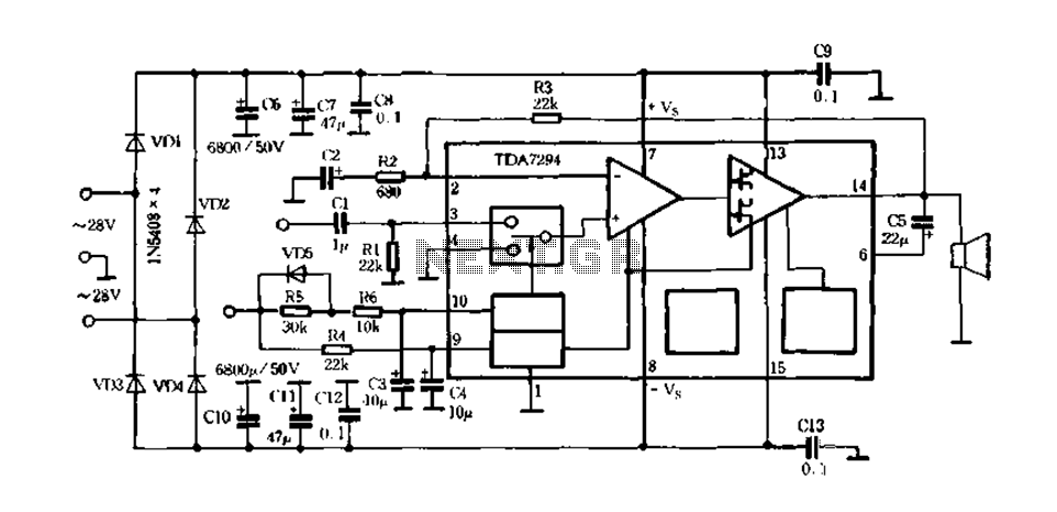
Europe's leading SGS-THOMSON STMicroelectronics recently introduced a new hydrazine fos power integrated amplifier, the TDA7294, to the Chinese mainland. This amplifier has surpassed traditional linear integrated amplifiers and has been successfully released for Hi-Fi applications, such as home theaters...
Utilize a V2-400 subwoofer amplifier for the center channel, and incorporate a separate Digital Converter specifically for the added subwoofer amplifier to initiate a V5.1 system. Place all preamplifiers within the subwoofer enclosure and design a digital control box...