
Computer Microphone preamp
In this circuit configuration, the PC sound card serves as the central hub for audio input and output. It is designed to accommodate a variety of inputs and outputs, including a microphone input, speaker output, and occasionally line inputs and outputs. The microphone input is specifically tailored for dynamic microphones, which typically operate within an impedance range of 200 to 600 ohms.
A notable modification in this setup is the adaptation of the sound card to accommodate a common electret microphone. This modification is facilitated by the implementation of a specific circuit design. The key component in this circuit is a composite amplifier, which is constructed using two transistors.
The first transistor, a BC413B, operates in a common emitter configuration. This setup allows the BC413B to amplify the microphone signal slightly, providing a modest boost to the audio input. Following this initial amplification stage, the signal is then passed to a second transistor, a BC547C.
The BC547C is configured in an emitter follower stage. This configuration is critical in ensuring the successful transmission of the microphone signal over a potentially significant distance to the sound card. This is due to the inherent characteristics of an emitter follower stage, which maintains a low output impedance.
The combination of the low output impedance of the circuit and the use of a screened cable helps to preserve the integrity of the microphone signal. It minimizes the risk of noise pickup, thus ensuring the delivery of a clean and clear audio signal to the sound card. This makes the circuit particularly suitable for situations where the microphone and battery source may be located some distance from the sound card.The sound card for a PC generally has a microphone input, speaker output and sometimes line inputs and outputs. The mic input is designed for dynamic microphones only in impedance range of 200 to 600 ohms. Lazar has adapted the sound card to use a common electret microphone using this circuit. He has made a composite amplifier using two transistors. The BC413B operates in common emitter to give a slight boost to the mic signal. This is followed by an emitter follower stage using the BC547C. This is necessary as the mic and circuit and battery will be some distance from the sound card, the low output impedance of the circuit and screened cable ensuring a clean signal with minimum noise pickup.
🔗 External reference
Related Circuits
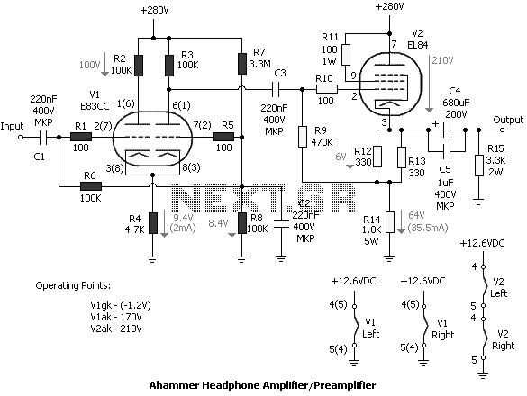
Tube amplifiers designed for headphones have the principal property that they can be used as preamplifiers too. In most cases, the output impedance of a tube headphone amplifier is (or should be) less than the output impedance of a...
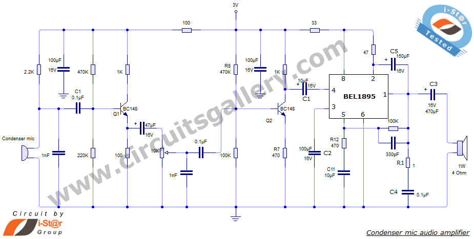
This document presents an audio amplifier circuit suitable for use in walkie-talkies, low-power transmitters, and packet radio receivers. The circuit utilizes a condenser microphone audio amplifier that delivers high-quality audio output of 0.5 watts at 3 volts. The design...
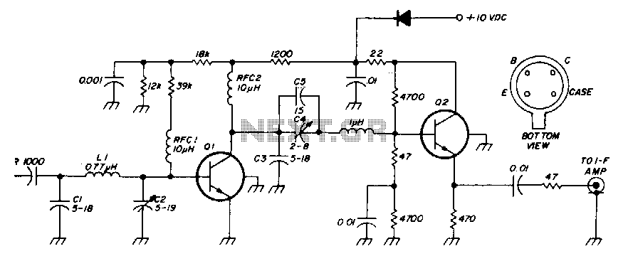
The low-noise preamplifier features a noise figure of 1 dB at 30 MHz and a 3 dB bandwidth of 10 MHz. The gain is 19 dB. The total current drain with a +10 volt supply is 13 mA. The...
Use microcontrollers to establish serial communication between the AVR-006 kit and a computer. This project utilizes the AVR-006 microcontroller from Circuits-Home. Before developing the program, it is essential to understand the hardware specifications. An example program (in C) for...
The circuit is shown in Figure 1, and as described above, uses a voltage doubler rectifier. Diodes D1 and D2 are 1N4004 or similar. From there, a pair of resistors provide additional smoothing to the secondary filter caps. R3...
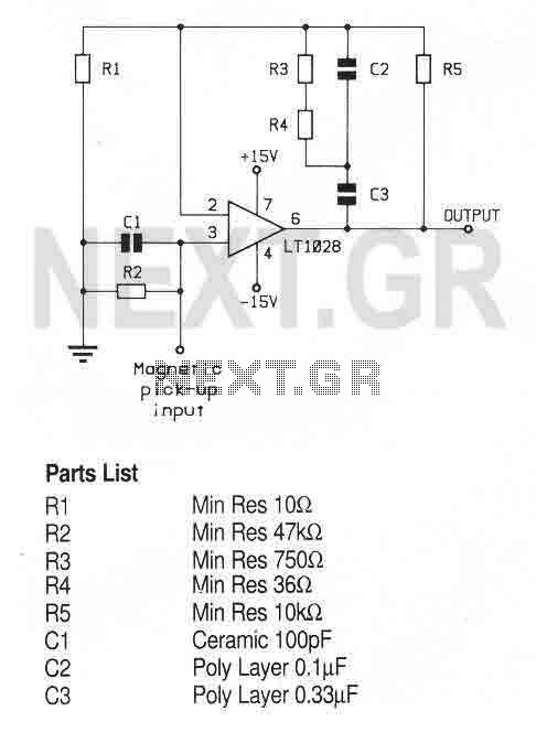
A high performance op-amp that sets a new standard of excellence in noise performance only 0.9nV/Hz with low source resistances. Total harmonic distortion is less than 0.01%. The op-amp is suitable for use in high quality audio, low noise...