
Phantom PS for Microphone

As can be seen, there are no adjustments, and this means that the 48V may be a little higher (or lower) than rated. This is not a problem however, and all phantom feed microphones will handle the variation without any problems at all.
Load regulation is far better than you might expect, with typically 100mV variation between full load (100mA) and no load. At 200mA load, the voltage falls by less than 150mV compared to the no-load voltage. Line (input) regulation is also quite good, with less than 200mV output change with +20% and -20% input voltage, with a load of 100mA.
The next problem is how to actually send the phantom power to the microphone and not the mixer input circuits. The latter will not be impressed with 48V DC applied, and will most likely voice their displeasure by failing instantly. The standard value of 6.81k (0.1% tolerance) for phantom feed circuits can be reduced to 6.8k (a standard E12 series resistor value), and it is suggested that using a multimeter to match the resistors to at least 0.1% is the easiest and cheapest alternative. Each pair of resistors should be matched to within 10 ohms (or less if possible) of each other for best results. This is better than 0.1%, and ensures that common mode performance is not compromised.
In case there is a concern about the claim that 10 ohms is better than 0.1%, a worst-case pair of 0.1% 6.81k resistors could have a difference of 13.62 ohms - one resistor at the maximum positive tolerance, and the other at maximum negative tolerance. Therefore, the closer the match, the better, and the multimeter used does not have to be absolutely accurate, since measuring for a difference rather than an absolute resistance value is sufficient. If the multimeter cannot measure to the required precision, alternative measuring methods may be found in the appendix.
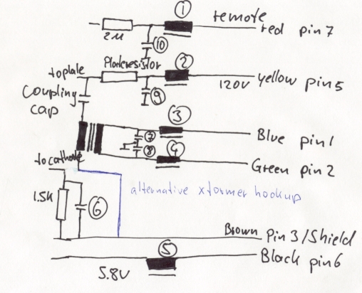
Figure 2 shows the basic phantom powering scheme. Only one channel is shown; subsequent channels are identical, up to a typical maximum of 10 (20 at a pinch) for a single supply module. It is extremely important that the transformer is not used to power other supplies or equipment. The center-tap must not be connected to anything and needs to be insulated to prevent contact. The supply circuit uses the full 30V AC in a floating configuration, and connection to another supply or rectifier will cause a short on the winding.
Q1 on the power supply (Figure 1) must be fitted with a heatsink, and worst-case power dissipation will be around 5W. This may not seem excessive, but a 10°C/W heatsink (typical of a large PCB mount type) will reach 50°C above ambient temperature (i.e., too hot) at 200mA output. At 100mA load, this is reduced to about 3W, which is more manageable. However, there is no such thing as a heatsink that is too large, so using the largest one possible is recommended. Forced air (fan) cooling will not be necessary.
The PCB layout is designed such that the power transistor can be attached directly to the chassis if desired (using insulating washers and heatsink compound, of course), alleviating the need for a separate heatsink. For only one or two phantom-powered microphones, a heatsink is not essential, but a small one is considered a prudent measure. In this case, R1 and R2 in Figure 1 may be increased in value, providing even better filtering. A 100-ohm resistor will be more than satisfactory for a two-microphone system.
Although bipolar electrolytic capacitors are shown, some constructors may prefer to use alternative capacitor types. However, polyester or similar capacitors at those values will be quite large. Assuming a microphone circuit input impedance of 1.2k (fairly typical), the two 22uF capacitors as shown will yield a -3dB frequency of 12Hz, which is necessary for a flat response to 20Hz. Naturally, if the lowest frequency required is higher, lower capacitance is acceptable. Likewise, if the microphone preamp input impedance is higher than 1.2k, less capacitance can also be utilized.The circuit is shown in Figure 1, and as described above, uses a voltage doubler rectifier. Diodes D1 and D2 are 1N4004 or similar. From there, a pair of resistors provide additional smoothing to the secondary filter caps. R3 is used to balance the voltage across C3 and C4, and must not be omitted. The regulator was a very common topology prior to the introduction of 3-terminal regulator ICs, and is used here so that high voltage regulators are not needed. These are much harder to get than the standard versions, and still require additional circuitry because 48V versions are not made.
Although the circuit looks complex, it is very easy to build (especially if the PCB is used). The zener diode is the reference voltage, and 1/2 the output voltage is compared to the zener voltage by Q3 (the error amplifier). If output voltage increases (because the load current is reduced for example), Q3 is turned on harder, removing base drive from Q2 (and hence Q1), reducing the output voltage to the preset value.
As can be seen, there are no adjustments, and this means that the 48V may be a little higher (or lower) than rated. This is not a problem however, and all phantom feed microphones will handle the variation without any problems at all.
Load regulation is far better than you might expect, with typically 100mV variation between full load (100mA) and no load. At 200mA load, the voltage falls by less than 150mV compared to the no-load voltage. Line (input) regulation is also quite good, with less than 200mV output change with +20% and -20% input voltage, with a load of 100mA.
The next problem is how to actually send the phantom power to the microphone and not the mixer input circuits. The latter will not be impressed with 48V DC applied, and will most likely voice their displeasure by failing instantly.
The standard value of 6.81k (0.1% tolerance) for phantom feed circuits can be reduced to 6.8k (a standard E12 series resistor value), and I suggest that using a multimeter to match the resistors to at least 0.1% is the easiest and cheapest alternative. Each pair of resistors should be matched to within 10 ohms (or less if possible) of each other for best results.
This is better than 0.1%, and ensures that common mode performance is not compromised. In case you were wondering about my claim that 10 ohms is better than 0.1%, a worst case pair of 0.1% 6.81k resistors could have a difference of 13.62 ohms - one resistor at the maximum positive tolerance, and the other at maximum negative tolerance. Fairly obviously, the closer the match the better, and the multimeter used does not have to be absolutely accurate, since you are measuring for a difference rather than an absolute resistance value.
If your multimeter refuses to measure to the number of digits needed, see the appendix for an alternative method you can use. Figure 2 shows the basic phantom powering scheme. Only one channel is shown - subsequent channels are identical, up to a typical maximum of 10 (20 at a pinch) for a single supply module.
It is extremely important that the transformer is not used to power other supplies or equipment. The centre-tap must not be connected to anything, and needs to be insulated to prevent contact. The supply circuit uses the full 30V AC in a floating configuration, and connection to another supply or rectifier will cause a short on the winding. Q1 on the power supply (Figure 1) must be fitted with a heatsink, and worst case power dissipation will be around 5W.
This may not seem like a great deal, but a 10°C/W heatsink (typical of a large PCB mount type) will get to 50°C above ambient temperature (i.e. too hot!) at 200mA output. At 100mA load, this is reduced to about 3W, which is a little more manageable. Even so, there is no such thing as a heatsink that is too big, so I suggest that you use the largest one that you can.
Forced air (fan) cooling will not be necessary. The PCB is laid out such that the power transistor can be attached directly to the chassis if desired (using insulating washers and heatsink compound, of course), and this alleviates the need for a separate heatsink. For only one or two phantom powered mics, a heatsink is not essential, but a small one is cheap insurance.
In this case, R1 and R2 in Figure 1 may be increased in value, and this will provide even better filtering. 100 ohms will be more than satisfactory for a two microphone system. Although shown using bipolar electrolytic caps, some constructors will no doubt want to use something 'better', but polyester or similar caps at those values will be very large!
Assuming a mic circuit input impedance of 1.2k (fairly typical), the two 22uF caps as shown will give a -3dB frequency of 12Hz - this is needed to get flat response to 20Hz. Naturally, if the lowest frequency you need is higher, then lower capacitance is acceptable. Likewise, if the mic preamp input impedance is higher than 1.2k, less capacitance can also be used. 🔗 External reference
Related Circuits

This design circuit is for a stereo amplifier intended for a high-sensitivity stereo parabolic microphone, enabling the listening of distant sounds. Unlike typical parabolic microphones that are monophonic, this unit features a stereo audio path, resulting in more realistic...
The microphone preamplifier circuit design presented in this schematic utilizes the SSM2015 component manufactured by Precision Monolithics Inc. (PMI). This component provides high amplification with low noise characteristics (1.3nV/f). The design is configured to handle differential input signals and...
The M7 capsule features a center-terminated, dual-diaphragm design and supports three polar patterns. A switch on the power supply allows for the selection of Cardioid, Figure-of-8, or Omnidirectional patterns. The amplifier circuit is reminiscent of Gefell's historical models, the...
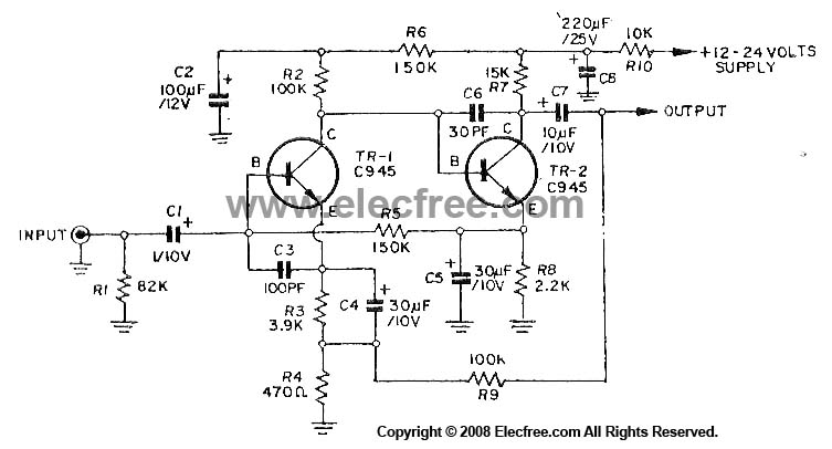
This circuit utilizes three transistors (2SC945, 2C1815, or 2SC828) as the primary components, functioning as a typical low-noise transistor amplifier. It offers a gain of approximately 200 to 300 times and has a frequency response ranging from 50Hz to...
The design consists of differential compound pairs of transistors with a common mode (floating) gain control connecting the emitters of the pair. The compound pairs of 2N4403 and BC549s are far more linear than any single transistor. The circuit...

This circuit was designed by Lazar Pancic from Yugoslavia. A typical PC sound card includes a microphone input, speaker output, and occasionally line inputs and outputs. The microphone input is specifically tailored for dynamic microphones with an impedance range...