
Connect Nokia 3310 LCD to LPT port

This circuit utilizes a Nokia 3310 graphical LCD, which is a compact and efficient display option commonly used in various electronic projects. The LPT (Line Printer Terminal) port serves as the communication interface between the computer and the LCD. The voltage level adjustment is crucial, as the LCD operates at a lower voltage than what the LPT port supplies. The inclusion of diodes in the circuit is a practical solution for voltage reduction; standard silicon diodes can be used to achieve the necessary voltage drop.
The schematic for this circuit should illustrate the connection points between the LPT port and the LCD. The LPT port typically has multiple pins, and the specific pins used will depend on the programming and data transmission requirements. The diodes should be placed in series with the power line to the LCD to ensure that the voltage does not exceed its maximum rating.
Once the hardware is assembled, the next step involves software configuration. The provided control program is essential for sending the appropriate signals to the LCD. The software must be compatible with the operating system in use; thus, users on Windows 2000 or XP should follow the guidelines for utilizing PortTalk, which facilitates direct access to the hardware ports.
To set up the software, after copying "allowio.exe" to the program directory, users should create a shortcut for the executable file (e.g., LCD.exe). Modifying the target line in the properties of this shortcut is necessary to ensure that the program runs with the required permissions to access the LPT port.
Overall, this circuit is an excellent example of interfacing legacy hardware with modern computing systems, showcasing both the simplicity and effectiveness of using basic electronic components and programming techniques to achieve desired functionality.I found this circuit really simple and interesting. It is really simple to drive Nokia 3310 graphical LCD by using simple LPT cable and some PC software. Firs of all connect graphical LCD to LPT port according to following circuit: Graphical display needs about 3.
3V of supply voltage, while LPT gives about 4. 5 -5V. This is why diodes are used to r educe voltage by formula: 4. 5V-0. 7V-0. 7V=3. 1V. When hardware part is done it is time to draw some images on LCD. For this download control program (Pascal source is included in package too). Software is written to drive ports directly in DOS or win98 operating system. If you are using Win2000 or XP you might want to read: Program LPT and COM ports easily under windows NT-2000-XP. Download PortTalk and unzip it in separate folder somewhere. Then copyallowio. exedirectly to the directory where is you program which you want to run. Then create shortcut of your compiled program for instance LCD. exe. Then open files properties and in line target do following changes: 🔗 External reference
Related Circuits
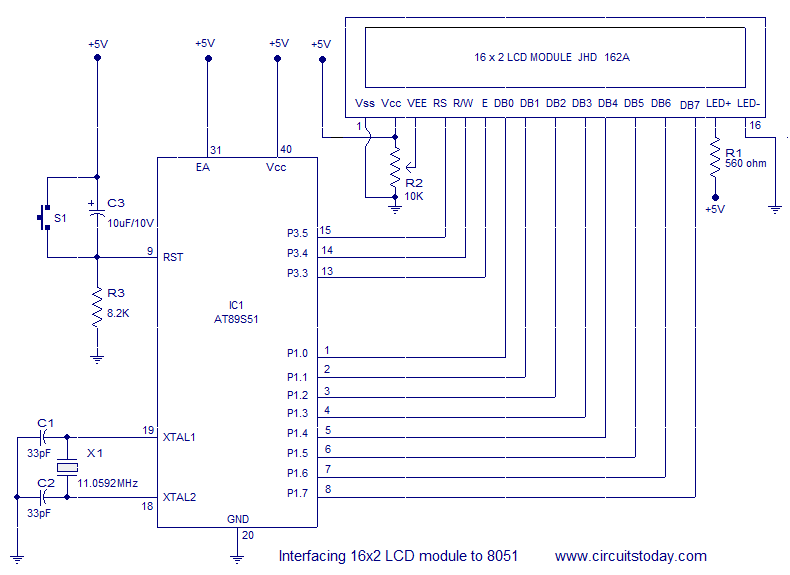
Interfacing a 16x2 alphanumeric LCD module with the AT89S51 microcontroller. The circuit diagram, theory, and program are included. JHD162 LCD module pinout and commands are provided. The integration of a 16x2 alphanumeric LCD module with the AT89S51 microcontroller involves several...
The reason why I am using an LCD display is because it allows me to display many characters and it doesn't need to be refreshed as 7-segment LED displays. Also, the interface requires less I/O pins. For this project,...

Laptop computers frequently utilize large-screen LCDs that require both a variable and a negative supply to achieve maximum contrast. This circuit operates from the system's positive battery supply and generates a digitally variable negative voltage to drive the display....
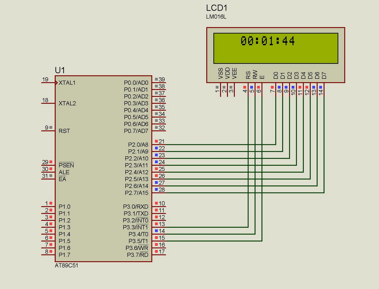
This project implements a real-time clock using the 89C51 microcontroller. The clock's data format is hours:minutes:seconds, which is displayed on a 16x2 LCD. The code has been tested and compiled using the Keil uVision compiler. The circuit diagram for...

This is an easy to build stepper motor driver that will allow you to precisely control a unipolar stepper motor through your computer's parallel port. With a stepper motor you can build a lot of interesting gadgets such as...
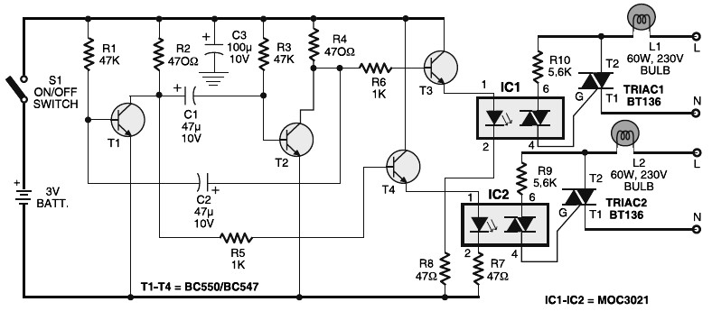
Portable 230V lamp flasher circuit diagram. The circuit is entirely transistorized and powered by a battery. A free-running oscillator circuit is implemented using two low-power, low-noise transistors, T1 and T2. One of these transistors remains in a conducting state...