
Portable 230V lamp flasher circuit diagram

The portable 230V lamp flasher circuit is designed for versatility and efficiency, making it suitable for a variety of applications, including decorative lighting and signaling. The use of a battery power source enhances its portability, allowing it to be used in locations without access to mains power. The oscillator's design is based on a multivibrator configuration that alternates the states of the transistors, effectively controlling the on-off operation of connected loads.
The adjustable frequency feature allows users to customize the flashing speed, which can be particularly useful for different aesthetic requirements or signaling purposes. The inclusion of variable resistors PR1 and PR2 for frequency and duty cycle adjustment adds to the circuit's flexibility, enabling fine-tuning to achieve the desired visual effects.
The circuit's reliance on low-noise transistors minimizes interference and enhances performance, making it ideal for applications where sound and light quality are critical. The specified component values, including resistors and capacitors, are chosen to optimize the performance of the oscillator and ensure stable operation across various conditions.
Furthermore, the incorporation of a SCR (Silicon Controlled Rectifier) in the design allows for controlled switching of higher voltages, making the circuit capable of handling significant AC loads. This feature is particularly advantageous for applications requiring robust performance and reliability.
Overall, the circuit's design emphasizes low-cost implementation, ease of assembly, and efficient operation, making it an excellent choice for hobbyists and professionals alike seeking a reliable lamp flasher solution.Portable 230V lamp flasher circuit diagram. The circuit is completely transistorised and battery-powered. The free-running oscillator circuit is realised working with two low-power, low-noise transistors T1 and T2. One of these two transistors is constantly conducting, whilst the other is blocking. Because of normal charging and discharging of cap acitors C1 and C2, both the transistors alternate between conduction and non-conduction states. This is a portable, 230V high-power incandescent electric lamp flasher circuit diagram. It is actually basically a double flasher (alternating blinker) which could manage two different 230V AC loads (bulb lamps L1 and L2). The circuit is completely transistorised and battery-powered. The free-running oscillator circuit is realised working with two low-power, low-noise transistors T1 and.
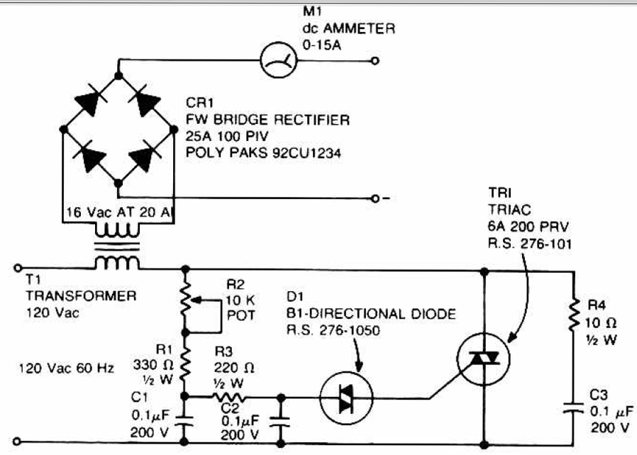
This is the 200W lamp flasher circuit diagram. The frequency/speed of the lamp flashing can be adjust with the range of 1Hz to 5Hz. You can use the PR1 variable resistor (trimpot) to adjust the flashing speed. The duty cycle of lamp flashing can be adjusted using PR2 variable resistor. The DC input power supply. This is low cost fully transistorised inverter circuit capable of driving medium loads of the order of 40 to 60 watts using battery of 12V, 15 Ah or higher capacity. Transistors T1 and T2 (BC548) form a 50Hz multivibrator. For obtaining correct frequency, the values of resistors R3 and R4 may have to be changed. This is a 220V LED flasher circuit which is intended as a reliable replacement to thermally-activated switches used for Christmas tree lamp-flashing.
This a cheap circuit and easy to build. Schematic diagram: Component Parts: R1_ 100K R2, R5_ 1K R3, R6_ 470R R4_ 12K C1_ 1000 µF 25V D1-D4_ 1N4007 D5_ SCR P0102D Q1_ BC327 Q2_ BC337 SK1_. The following is LED Flasher circuit which use 2 transistors for LED switching. The circuit works similar to flip-flop operation. Component Parts List: R1 = 10M ohm R2 = 1K - 100K ohm R3 = 470 ohm C1 = 0. 47 F - 10 F/25V D1 = 1N914 Q1 = 2N3904 Q2 = 2N3906 Led = High Brightness. This circuit consume low current supply (about 2mA), so will have a long battery life for supplying the circuit.
The circuit built based on a low noise, high gain two stage PNP and NPN transistor amplifier, using DC negative feedback through R6 to stabilize the working conditions quite precisely. 🔗 External reference
Related Circuits

There are many digital thermometers with ±1°C displays, but their accuracy is approximately ±1°C and they cannot be calibrated. A thermometer circuit was created using components available at a local electronics hobby shop, providing an educational experience. For a...
Low-cost water pump controller circuit. The sensors used in the circuit can be any two conductive probes, preferably resistant to electrolytic corrosion. For example, a suitably sealed audio jack can be employed as the sensor. The automatic pump controller...
The SL517 is designed as an audio, RF, or infrared decoder circuit suitable for electronic toy applications. The internal circuitry consists of an analog amplifier, a frequency divider, a bistable circuit, and a driver. It utilizes CMOS technology, has...
This circuit can be used to charge accumulator and cell batteries. It features a very stable output that extends the battery life and maximizes the added battery capacity. The charging process is also quite fast, optimizing the time required...

Burst Mode operation maintains high efficiency at light loads by reducing IC quiescent current to 120 µA. Light load efficiency is also improved with the reverse inductor current inhibit function, which supports discontinuous operation. Additional features include an adjustable...

The passive tone control circuit is designed to adjust the bass without expansion, utilizing resistors (R) and capacitors (C). It functions as a frequency filter and is easy to construct, requiring no external power supply. This circuit can be...