
Connection circuit diagram of four-wire ballast in fluorescent

The four-wire ballast system is integral to the operation of fluorescent lighting, enabling efficient energy transfer and reliable lamp ignition. The main coil typically comprises two leads that are connected in series with the fluorescent lamp and the power supply, ensuring that the lamp receives the necessary voltage and current for operation. This configuration is crucial for maintaining the correct operating conditions within the lamp.
The auxiliary coil, on the other hand, serves a distinct purpose. The two leads from the auxiliary coil are connected to the starter and the fluorescent tube. The starter is responsible for initiating the lamp's operation by generating a high-voltage pulse that ionizes the gas within the tube. This ionization allows current to flow through the lamp, enabling it to illuminate. The auxiliary coil thus plays a critical role in the lamp's starting sequence, ensuring that the lamp ignites reliably.
In summary, the four-wire ballast connection is a sophisticated arrangement that enhances the performance and reliability of fluorescent lighting systems. By understanding the roles of both the main and auxiliary coils, one can appreciate the complexity and efficiency of fluorescent lamp technology.Four-wire ballast connection of fluorescent There are four lead wires in four-wire ballast, including main and auxiliary coils. The connection of two lead wires in main coil is the same with second-line ballast, both of them connect between the lamp and power supply in series.
The two lead wires in auxiliary coil connect between the starter and the tube in.. 🔗 External reference
Related Circuits
A newer version of this circuit board is available. Rev 4 includes a faster CPU, more memory, more I/O, and an optional LCD. It is recommended to use Rev 4 for new projects. Although the older board is no...

Several integrated circuits (ICs) are currently available that provide a nearly complete FM receiver solution. This project outlines a complete FM receiver circuit that offers excellent receiving and sound qualities. However, from a DIY enthusiast's perspective, the only drawback...

This switch utilizes four CD4013BE dual flip-flops, an inverter, and an optoisolator to control a triac, allowing it to switch a 25-A AC load current. A standard 4x3 telephone keypad is employed for entering a 6-digit code. In the...

A photocell circuit provides automatic threshold adjustment. Monostable action prevents undesired retriggering of the output. With only one op amp IC, the circuit offers automatic adjustment of its trigger level to accommodate various light sources, changes in ambient light,...
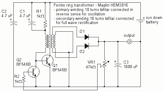
How to create a Joule Thief circuit to power a clock, including circuit details and tips for construction. The Joule Thief circuit is a simple and efficient boost converter that allows the extraction of usable voltage from low-voltage sources, such...
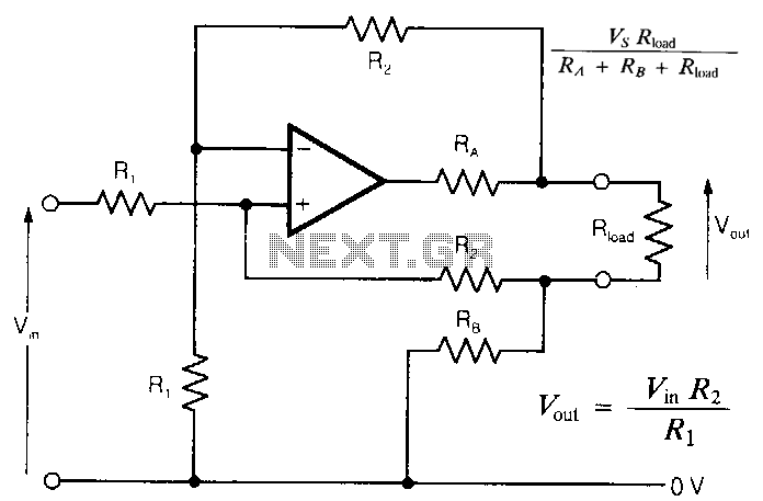
In intrinsically safe applications, it is sometimes necessary to separate sections of circuitry using resistors that limit current under fault conditions. The circuit presented offers an accurate analog output with effectively zero output impedance, despite the presence of resistors...