
Joule thief circuit powering a clock

The Joule Thief circuit is a simple and efficient boost converter that allows the extraction of usable voltage from low-voltage sources, such as depleted batteries. This circuit is particularly useful for powering devices like clocks that require a minimal amount of current.
To construct a Joule Thief circuit for powering a clock, the following components are typically required:
1. **Transistor (e.g., 2N3904 or BC547)**: This acts as the primary switching element, allowing the circuit to boost the voltage.
2. **Inductor (e.g., 100 µH)**: A ferrite core inductor is commonly used, which plays a crucial role in energy storage and voltage boosting.
3. **Resistor (e.g., 1 kΩ)**: This resistor is used to limit the base current to the transistor.
4. **Diode (e.g., 1N4148)**: A fast-switching diode is necessary to rectify the output voltage and prevent backflow of current.
5. **Capacitor (optional)**: A small capacitor can be added at the output to stabilize the voltage.
The circuit operates by charging the inductor when the transistor is in the "on" state. Once the transistor switches off, the magnetic field in the inductor collapses, inducing a higher voltage across the inductor. This boosted voltage can then be rectified by the diode and used to power the clock.
For optimal performance, it is advised to ensure that the inductor is properly wound with the appropriate number of turns (typically around 30-40 turns of enamel-coated copper wire around a ferrite core). The circuit should be tested with different values of resistors to find the best base current for the transistor, ensuring efficient switching and minimal power loss.
When integrating this circuit with a clock, it is essential to verify that the output voltage meets the clock's requirements, usually around 1.5V to 3V. This can be achieved by adjusting the number of turns on the inductor or modifying the resistor values.
Overall, the Joule Thief circuit is an excellent solution for extending the life of low-voltage batteries while providing a reliable power source for low-power devices like clocks. Proper assembly and component selection are crucial for achieving optimal functionality.How to make a joule thief circuit power a clock. The circuit and Tips for making it. 🔗 External reference
Related Circuits
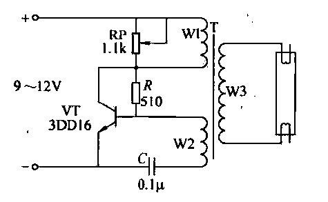
This circuit is designed for the ignition of a direct current (DC) fluorescent lamp rated between 6 to 8 watts. It utilizes a common pole-blocking oscillator that consists of a transistor (VT) and is induced by the secondary side...
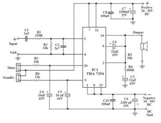
This audio amplifier circuit utilizes the TDA7294, a power integrated circuit designed for high-quality audio applications. The TDA7294 operates as a class AB amplifier, characterized by low noise and distortion levels, a wide bandwidth, and robust output current capability....
A relay (RL1) is activated with a 100-second delay when a +12V power supply is connected to the circuit. Figure 2 illustrates a relay timer circuit utilizing a 555 timer, featuring two time ranges: 6-60 seconds and 1-10 minutes...
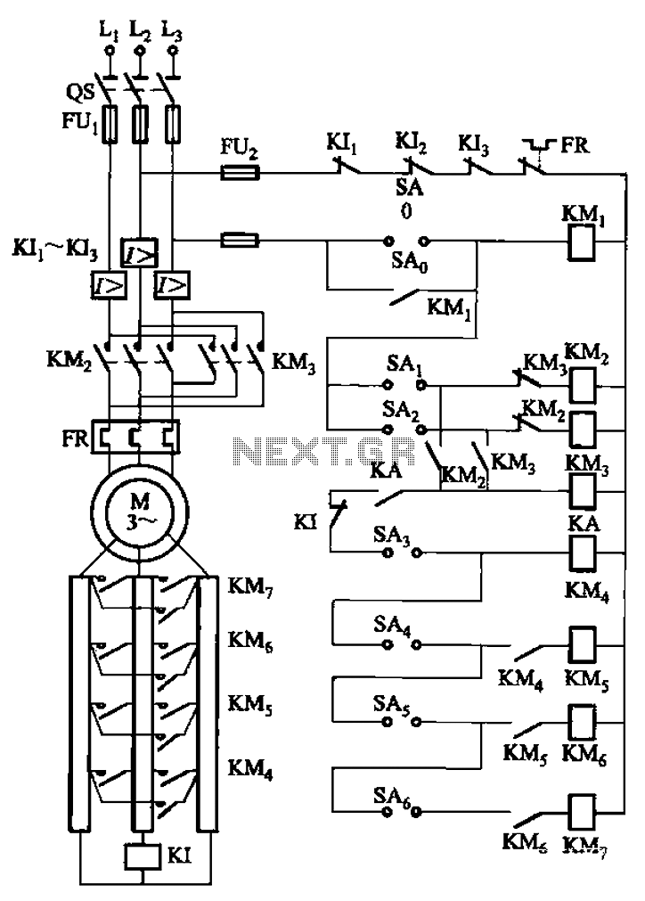
The circuit depicted in Figure 3-168 utilizes a controller for speed grading and reversing control. A reverse brake is connected to the rotor circuit through an overcurrent relay, labeled KI, for control. The current relay KIi to KI3 serves...
This compact video transmitter is highly useful for video surveillance over short distances (up to 100 meters) and is equipped with either a black and white or infrared camera module. The compact video transmitter is designed for efficient video surveillance...
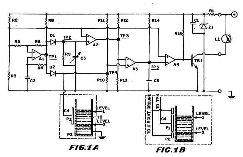
Figure 1 (A) depicts the circuit diagram of one embodiment of the fluid level detector designed. The circuit is typically powered by a 12-volt automobile battery, which is reduced to a 5-volt DC source using a voltage regulator consisting...