
Connection Tester

This circuit design operates effectively as a continuity tester, leveraging the differential amplification capabilities of the 741 op-amp. The circuit configuration consists of the op-amp, two input probes, a 470kΩ resistor, a 10kΩ variable resistor, and a pair of LEDs for visual indication. The continuity tester is designed to detect low resistances, typically in the range of 0.22Ω to 4Ω.
Upon connecting the probes to the resistor, the 10kΩ control is adjusted to achieve a threshold where the LEDs just illuminate. This adjustment is critical for calibrating the circuit to ensure sensitivity to low resistance values. Once calibrated, removing the resistor and shorting the probes should result in the LEDs turning off, indicating successful operation.
To enhance performance and reliability, it is important to maintain clean contact surfaces on the probes, as contamination can introduce unwanted resistance, affecting the circuit's accuracy. The versatility of the circuit is notable, as it can accommodate various op-amp types, including MOSFET and JFET configurations, broadening its applicability in different electronic testing scenarios.
In instances where the LEDs remain illuminated after shorting the probes, a 10kΩ preset resistor can be employed across the offset null terminals of the op-amp to fine-tune the output and restore normal operation. This adjustment allows for compensation of any inherent offset voltage, ensuring the circuit functions correctly across a range of conditions.
Overall, this continuity tester circuit represents a practical and efficient solution for measuring low resistances in electronic applications, with straightforward calibration and maintenance requirements.This simple circuit uses a 741 op-amp in differential mode as a continuity tester. The voltage difference between the non-inverting and inverting inputs is amplified by the full open loop gain of the op-amp. Ignore the 470k and the 10k control for the moment, and look at the input of the op-amp. If the resistors were perfectly matched, then the vo ltage difference would be zero and output zero. However the use of the 470k and 10k control allows a small potential difference to be applied across the op-amp inputs and upset the balance of the circuit. This is amplified causing the op-amp output to swing to full supply voltage and light the LED`s. The probes should first be connected to a resistor of value between 0. 22 ohm and 4ohm. The control is adjusted until the LED`s just light with the resistance across the probes. The resistor should then be removed and probes short circuited, the LED`s should go out. As the low resistance value is extremely low, it is important that the probes, (whether crocodile clips or needles etc) be kept clean, otherwise dirt can increase contact resistance and cause the circuit to mis-operate.
The circuit should also work with a MOSFET type op-amp such as CA3130, CA3140, and JFET types, e. g. LF351. If the lED`s will not extinguish then a 10k preset should be wired across the offset null terminals, pins 1 and 5, the wiper of the control being connected to the negative battery terminal. A pin out for the 741 can also be found here 🔗 External reference
Related Circuits
This network wiring tester consists of two components: a transmitter unit, which is powered and installed at the network's starting point, and a passive receiver unit that can be moved from socket to socket. Both units contain eight LEDs,...
This circuit utilizes the widely available and user-friendly LM3914 integrated circuit (IC). The LM3914 is straightforward to operate, does not require external voltage regulators due to its built-in voltage regulation, and can be powered by nearly any voltage source....
This little guide for every electronics tester would actually have to lie in the toolbox. You can have components such as resistors, capacitors, diodes, etc. of testing. T1 and T2 form a Darlington. Therefore only need a small base...
This compact Infrared Remote Control Tester circuit is designed to verify the functionality of an infrared remote control unit. The circuit operates by connecting a piezo buzzer directly to an IR receiver integrated circuit (IC). The TSOP1738 integrated IR...
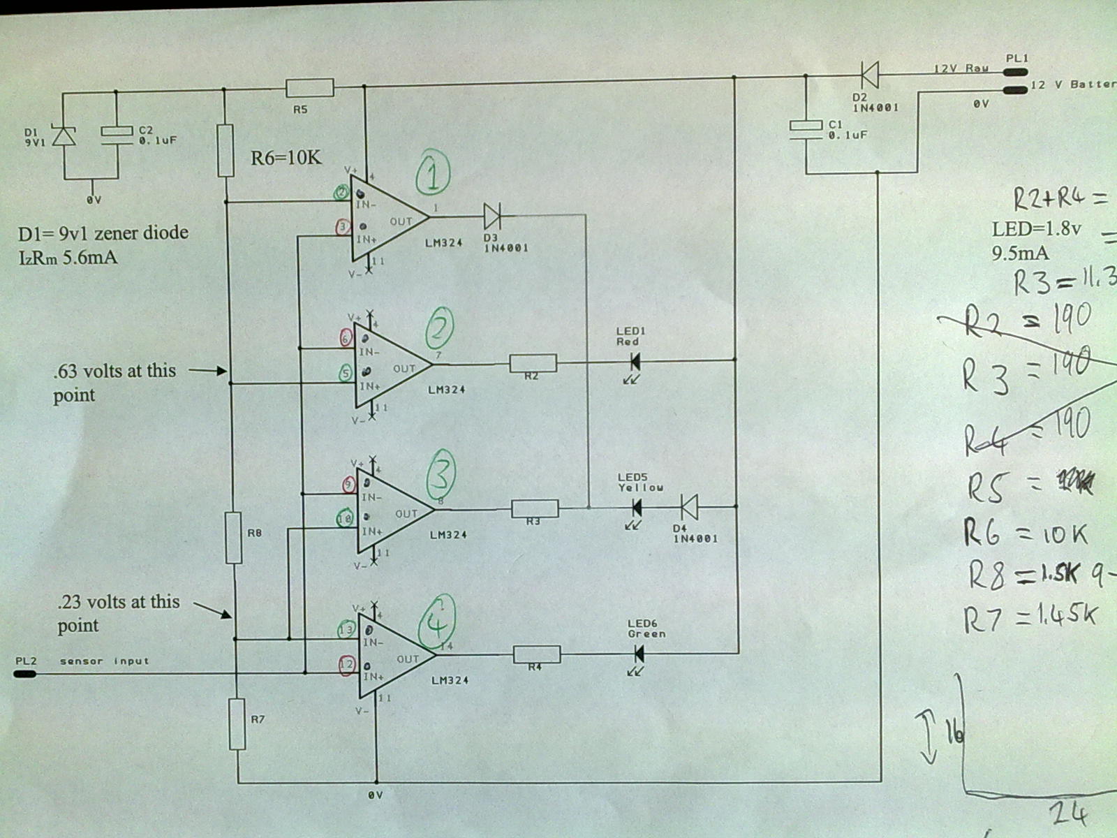
A 12V power supply is connected to the positive terminal, allowing current to flow through a protection diode and a capacitor that smooths the voltage. A zener resistor (R5) limits the current to the zener diode, which regulates the...
The 4017 traffic light circuit connects four legs to the green LED and two legs to the amber LED. This configuration raises the question of whether it could function with only one leg per LED. Each output is activated...