
Conductivity Tester circuit

R1 = 100 kΩ
R2 = 1 MΩ ½
R3 = 10 kΩ
R4 = 220 Ω
D1 = LED red
T1, T2 = 547 BC
The described circuit functions as a basic electronic tester for resistors and capacitors, leveraging a Darlington pair configuration formed by transistors T1 and T2 (BC547). This configuration allows for high current gain, enabling the circuit to operate effectively even with minimal base current. The presence of the LED (D1) provides a visual indication of the circuit's operational status.
In the testing mode for resistors, the circuit can accommodate resistances up to 2 MΩ. When a resistor is connected across the leads, the current flowing through the resistive element causes the LED to light up, confirming the functionality of the resistor. Resistor R1 (100 kΩ) serves as a current-limiting resistor for the LED, ensuring that it operates within safe limits.
For capacitor testing, the circuit is designed to briefly illuminate the LED when a capacitor is connected. The duration of the LED's illumination depends on the capacitor's value; larger capacitances will result in a longer discharge time, causing the LED to remain lit for a more extended period before extinguishing. It is essential to note that electrolytic capacitors have polarity, and incorrect connections may lead to erroneous readings or damage.
Resistor R2 (1 MΩ) is utilized to provide a discharge path for the capacitor, while R3 (10 kΩ) and R4 (220 Ω) are included to stabilize the circuit and set the appropriate biasing conditions for the transistors in the Darlington pair. The sensitivity of the circuit is such that even slight contact between the test leads can cause the LED to illuminate, indicating the high gain characteristic of the Darlington configuration.
This electronic tester is a valuable tool for hobbyists and professionals alike, providing a compact and efficient means to test basic electronic components directly from a toolbox.This little guide for every electronics tester would actually have to lie in the toolbox. You can have components such as resistors, capacitors, diodes, etc. of testing. T1 and T2 form a Darlington. Therefore only need a small base current to run and the LED is already lit. The tester is suitable for up to 2 M? resistors. The tester is also suitable for capacitors. When a capacitor is connected to the leads, the LED, depending on capacity, light briefly and then to extinguish. When electrolytic capacitors have polarity. The circuit is so sensitive that even the LED lights when the contacts between the fingers touched. Note that this does not happen during testing. R1 = 100 kOhm R2 = 1 M ½ R3 = 10kW R4 = 220 ? D1 = LED red T1, T2 = 547 BC 🔗 External reference
Related Circuits
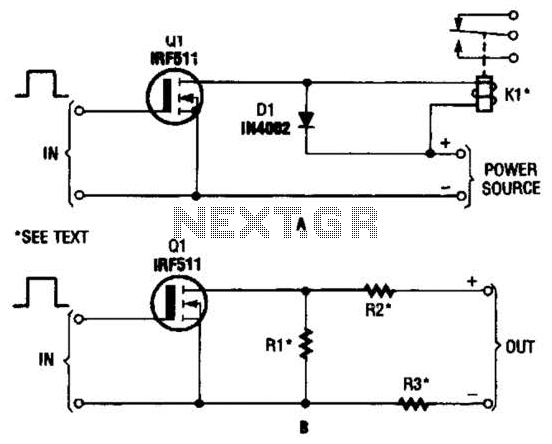
The hexFET can switch DC power to relays, motors, lamps, and various other devices. This configuration can also be utilized to switch resistors in and out of a circuit. R1, R2, and R3 represent resistive loads that can be...
This module utilizes an unconventional topology while retaining the fundamental operational amplifier circuitry of the main module, with some modifications in resistor values. A distinctive feature of this circuit is the incorporation of six-way switches instead of the more...
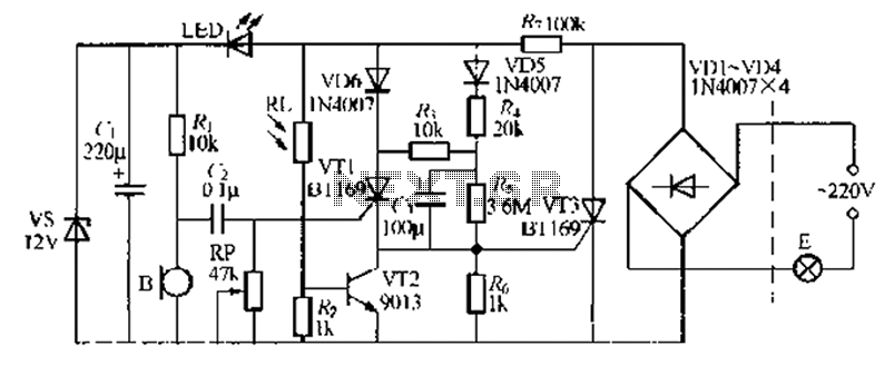
A relatively simple circuit for controlling a stair walkway light with a delay feature. The circuit has a drawback in that the voice activation is somewhat less sensitive, making it sometimes difficult to trigger with general conversation. However, it...
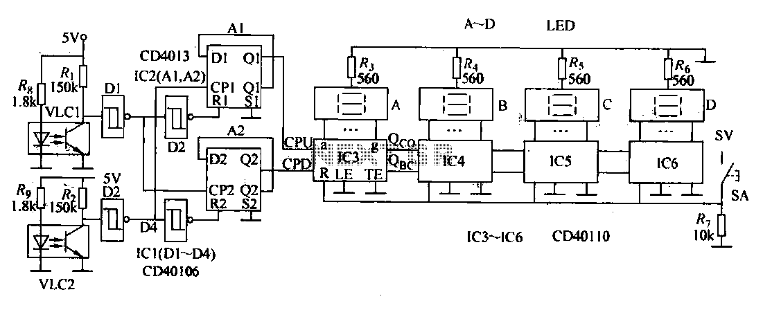
This document describes an electronic winding machine with manual, electric, and semi-automatic features. The specific example highlighted includes an electronic counting function that assists users in managing motor windings. The circuit design consists of various components as illustrated in...
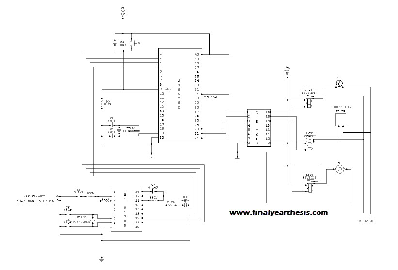
The objective of the project is to create a system that utilizes mobile technology to manage various home appliances based on signals sent from a mobile device. This innovative concept allows for the remote control of appliances through GSM...
The Johnson 275 watt and Kilowatt Matchboxes are often seen as exaggerated and unfairly criticized. They are neither exceptional tuners nor poorly designed. The main drawbacks include the fixed coupling link and the fact that they are balanced voltage...