
Connection Tester

The continuity tester circuit described utilizes a 741 operational amplifier (op-amp) configured in a differential mode to detect low resistances typically found in soldered joints and connections. The operational amplifier's differential input allows for the measurement of small voltage differences, which are indicative of continuity in the circuit being tested.
In the absence of any applied resistance, the circuit is designed such that the voltage difference between the non-inverting (+) and inverting (-) inputs of the op-amp is ideally zero. Under these conditions, the output of the op-amp remains at zero volts. However, the introduction of a 470kΩ resistor and a 10kΩ potentiometer serves to create a small imbalance in the input voltages. This imbalance is crucial as it allows for the detection of low resistance values.
When a low resistance (between 0.25Ω and 4Ω) is present across the test leads, it generates a slight voltage difference that is amplified by the op-amp's open-loop gain. The output of the op-amp will then swing towards the supply voltage, which can be used to drive an indicator, such as an LED. The LED acts as a visual indicator of continuity, lighting up when a connection is established.
The selection of the 470kΩ and 10kΩ components is essential for adjusting the sensitivity of the circuit. The potentiometer can be calibrated to fine-tune the threshold at which the LED will illuminate, allowing for flexibility in testing various types of connections and solder joints. This simple yet effective circuit design provides an efficient means of verifying electrical connections, ensuring reliable performance in electronic assemblies.A low resistance ( 0.25 - 4 ohm) continuity tester for checking soldered joints and connections. This simple circuit uses a 741 op-amp in differential mode as a continuity tester. The voltage difference between the non-inverting and inverting inputs is amplified by the full open loop gain of the op-amp. Ignore the 470k and the 10k control for the moment, and look at the input of the op-amp. If the resistors were perfectly matched, then the voltage difference would be zero and output zero. However the use of the 470k and 10k control allows a small potential difference to be applied across the op-amp inputs and upset the balance of the circuit. This is amplified causing the op-amp output to swing to full supply voltage and light the LED' 🔗 External reference
Related Circuits

This circuit is an Infra-Red Remote Control Tester designed to verify the functionality of any remote control that transmits infrared (IR) light. It operates on a 3V battery and offers several advantages, such as its compact size and the...
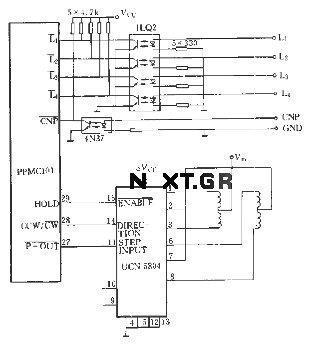
The PPMC external UChl 5804 demonstrates a four-phase stepping motor drive integrated circuit (IC) that is depicted in a downward motion. It utilizes the P-OUT, counterclockwise (ccw) / clockwise (cw), and HOLD outputs. The UCN5804 pins 9 and 10...

The circuit diagram represents a useful tool for quickly testing various types of thyristors, including silicon-controlled rectifiers (SCRs) and triacs. For triacs, all four quadrants are assessed using switch S3, while testing a standard thyristor requires the adjustment of...
This simple circuit is designed to test transistors in a circuit, capable of measuring down to 40 ohms across the collector-base or base-emitter junctions. It is also suitable for checking output power transistors in amplifier circuits. The operation of...
This simple device checks if there is water in a pot plant. You stick the two probes (paperclips) into the pot plant and if the LED lights, it means there is water in the pot plant. The described device operates...
The UTP Cable Tester is designed for multiple applications, primarily to test UTP network cables. It can also assist in identifying the correct cable from a large bundle of similar cables. The circuit can be adapted to test any...