
PPMC and stepping motor driver IC dedicated connection circuit

The PPMC external UChl 5804 is designed to control a four-phase stepping motor through a series of outputs that facilitate various operational modes. The P-OUT output serves as the primary control signal for the motor, while the ccw and cw outputs determine the rotational direction of the motor. The HOLD output is utilized to maintain the motor's position when not actively stepping, reducing power consumption and preventing unwanted movement.
The UCN5804 integrated circuit is a versatile component that supports multiple configurations for motor operation. By employing pins 9 and 10, the circuit can be adjusted to operate in a two-phase tuning step mode, which allows for finer control of the motor's position and speed. Additionally, the IC can be configured for single-phase full-step and half-step modes, providing flexibility in the motor's performance based on the application's requirements.
The schematic includes an optocoupler connection to five limit switches, which are critical for ensuring that the motor does not exceed its designated range of motion. The limit switches provide feedback to the control system, enabling it to stop the motor when it reaches a predefined position. This integration enhances the safety and reliability of the system, preventing damage to the motor and associated components.
Overall, the PPMC external UChl 5804 and its associated circuitry represent a sophisticated approach to controlling stepping motors, offering a range of operational modes and safety features that are essential for precise motor control in various applications.PPMC external UChl 5804 shows four-phase stepping motor drive IC is shown moving down. It uses the P-OUT, ccw / cw and HOLD output. Use UCN5804 9 and 10 pin logic level can be set up as a two-phase motor tuning step, single-phase full-step, half-step and other incentives in three different sports. In this figure, it was shown by the optocoupler connection between the five limit switches and PPMC.
Related Circuits
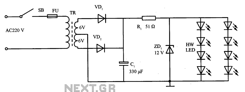
The schematic for the LED lighting circuit in a refrigerator consists of eight high-brightness white LED lights. These LEDs are housed in a transparent white plastic tube, which is the same height as the refrigerator cabinet. The circuit receives...
This is a variable power supply controlled by a PIC microcontroller. An LCD display is included in the circuit to show the actual output voltage and current values. A push-button switch is used to adjust the output voltage and...
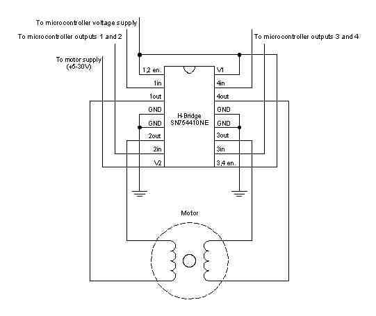
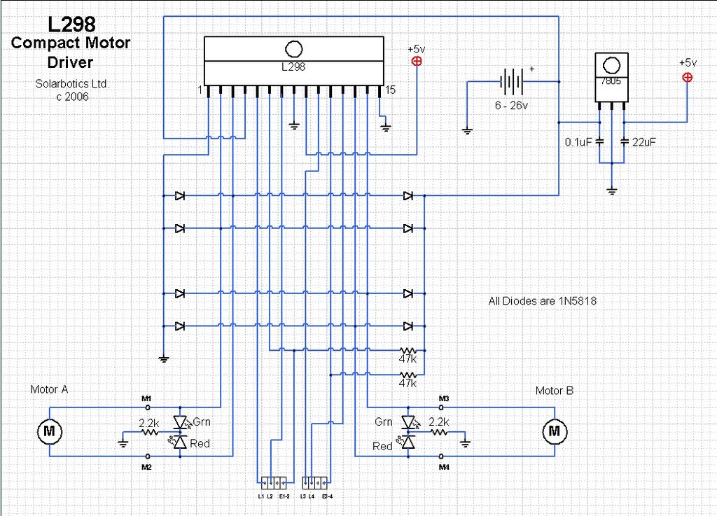
A stepper motor is a motor controlled by a series of electromagnetic coils. The center shaft has a series of magnets mounted on it, and the coils surrounding the shaft are alternately energized or de-energized, creating magnetic fields that...
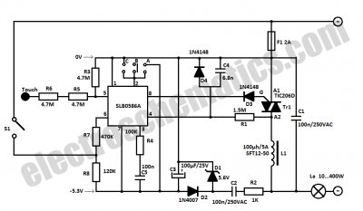
This light dimmer control features active timing capacitor reset or AC line zero-crossing synchronization. The 13 additional components are common and cost less than $2. Performance at the low end is exceptionally smooth and snap-free, even better than the...
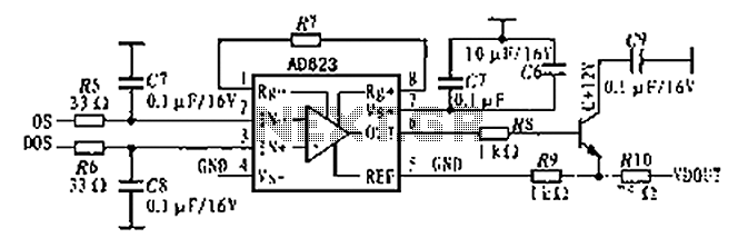
The AD623 is an integrated 3-way amplifier that can operate with either a single or dual supply. It features high common-mode rejection ratio (CMRR) and low voltage drift, along with programmable gain control via an external resistor. All components...
The ArduinoISP Bootloader/Programmer Combination Shield (not displayed) works with an Arduino equipped with a USB to serial chip (e.g., Arduino Uno) to upload the bootloader and sketches to a DIYduino. A USB to Serial programmer can also be utilized...