
Constituted by the ISO113 0 ~ 20mA current loop isolation drive circuit diagram

The ISO113 current loop isolation drive circuit is designed to provide electrical isolation between the input and output, ensuring that any noise or interference present in the input signal does not affect the output. This is particularly important in industrial environments where electromagnetic interference (EMI) is common. The twisted pair configuration of the load resistor (RL) further enhances noise immunity, allowing for stable current transmission over extended distances.
The XTR101 plays a crucial role in this circuit by converting the input voltage signal into a proportional current output within the 0 to 20 mA range. This current is standard in many industrial applications, allowing for compatibility with a wide range of sensors and devices. The 4 to 20 mA current loop is a widely accepted standard for transmitting analog signals, where 4 mA typically represents the minimum measurement and 20 mA the maximum, facilitating easy interpretation of the signal levels.
The RCV420 receiver is designed to accurately detect the current flowing through the loop and convert it into a voltage signal suitable for further processing. This voltage signal can then be utilized by various control systems or monitoring equipment. The ISO103 isolation amplifier provides additional isolation, ensuring that any variations in the load do not affect the measurement accuracy or the integrity of the signal being processed.
Overall, this circuit configuration is ideal for applications requiring reliable and accurate signal transmission over long distances, ensuring that the integrity of the data is maintained while minimizing the risk of interference. As shown in FIG constituted by ISO113 0 ~ 20mA current loop isolation drive circuit. VIN signal input ISO113 isolation amplified output 0 ~ 20mA current to the load through the twisted pair RL, the 4 ~ 20mA current loop precision receivers RCV420 receives converted into a voltage signal to the isolation amplifier ISO103. The main features of this circuit is using XTR101 input signal into 0 ~ 20mA current, long-distance transmission current signals without susceptible to interference.
Related Circuits
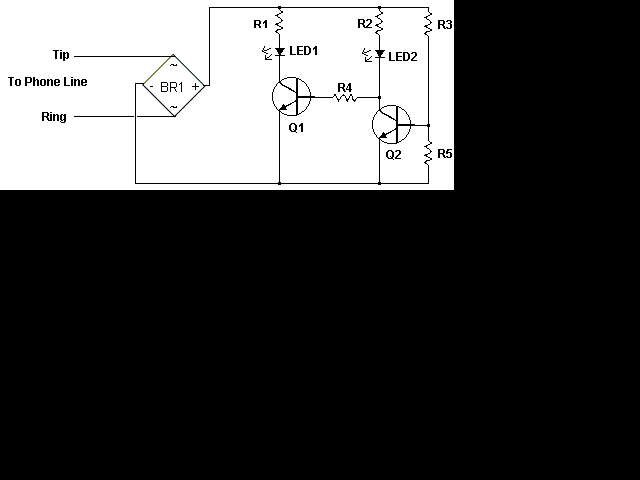
This circuit addresses the issue of phone line interruptions caused by simultaneous use of a modem or fax machine when another phone is picked up. It indicates the status of the phone line by illuminating a red LED when...
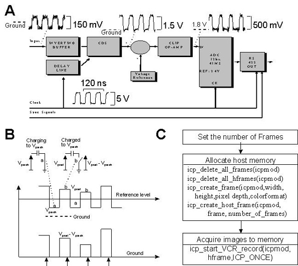
This document provides technical details regarding the hardware and software of a complete imaging system that utilizes a fast CCD sensor and a 41 Msample/s A/D converter. This system is capable of acquiring full-frame digitized images at a resolution...
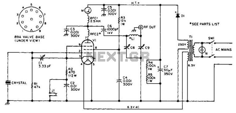
This transmitter operates on a 9-V battery and can function as a wireless microphone compatible with standard 88- to 108-MHz FM broadcast receivers. To adhere to FCC regulations, the antenna length should not exceed 12 inches. The inductor L1...
This circuit employs an astable multivibrator to alter the state of a signal based on specific conditions. It also incorporates a flip-flop, which retains the state of the output once a change is detected, completing a cycle of the...
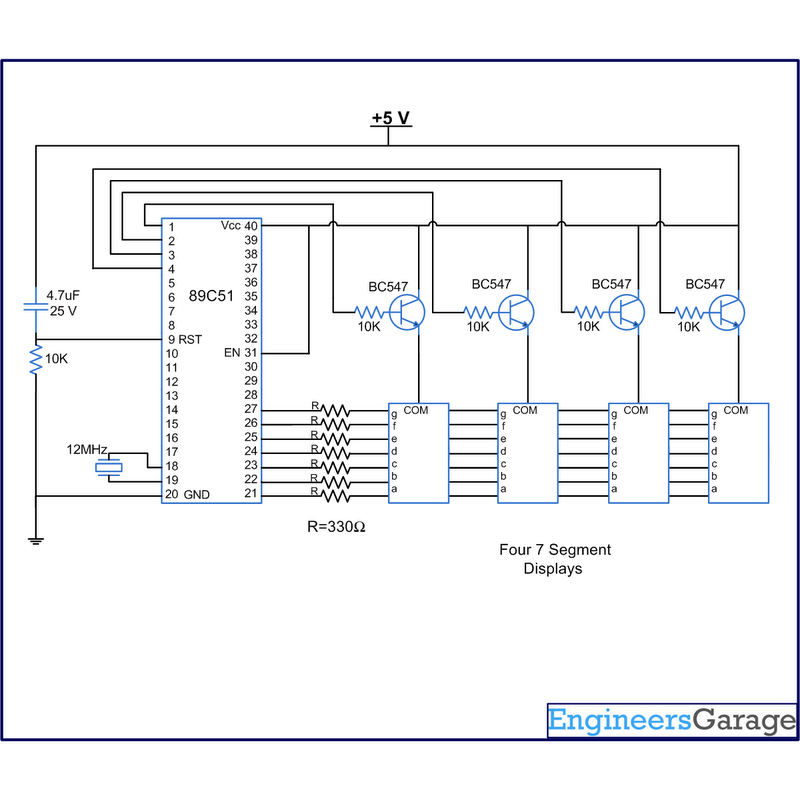
A digital clock displays time in a digital format. The circuit outlined here shows the time with double-digit minutes and two digits for seconds across four seven-segment displays. The segments of the displays are interconnected with the 8051 microcontroller...
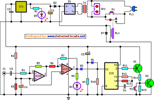
This circuit deactivates an amplifier or any connected device when a low-level audio signal is absent at its input for at least 15 minutes. Activating switch P1 powers the device, enabling operation of any appliance connected to SK1. The...