
phone busy circuit

The circuit utilizes a simple design that can be implemented with basic electronic components. It typically includes a pair of light-emitting diodes (LEDs), a resistor, and a few passive components to detect the phone line's status. The red LED serves as a visual warning to indicate that the line is currently in use, while the green LED provides a clear signal that the line is free for use.
When the phone is in use, the circuit detects the voltage drop across the phone line, which occurs when a phone is off-hook. This change in voltage activates the red LED, signaling that the connection is active. Conversely, when the phone is on-hook, the circuit detects the higher voltage level, which activates the green LED, indicating that the line is available.
The circuit's design is compact, making it suitable for installation within the phone housing or along the phone line. This placement allows for unobtrusive monitoring of the phone line status without the need for additional power sources, as it draws power directly from the phone line itself. The use of low-power LEDs ensures that the circuit operates efficiently without affecting the overall performance of the phone system.
Overall, this circuit provides a practical solution for users of modems and fax machines, enhancing communication reliability by visually indicating the status of the phone line and preventing disconnections during critical operations.Have you ever been using the modem or fax and someone else picks up the phone, breaking the connection Well, this simple circuit should put an end to that. It signals that the phone is in use by lighting a red LED. When the phone is not in use, a green LED is lit. It needs no external power and can be connected anywhere on the phone line, even mo unted inside the phone. 🔗 External reference
Related Circuits
This site addresses a range of subjects pertaining to circuits and electronics. Some of the topics discussed on this site include: * Alternating Relay Switch * Photoswitch Relay. The site serves as a comprehensive resource for understanding various electronic components...
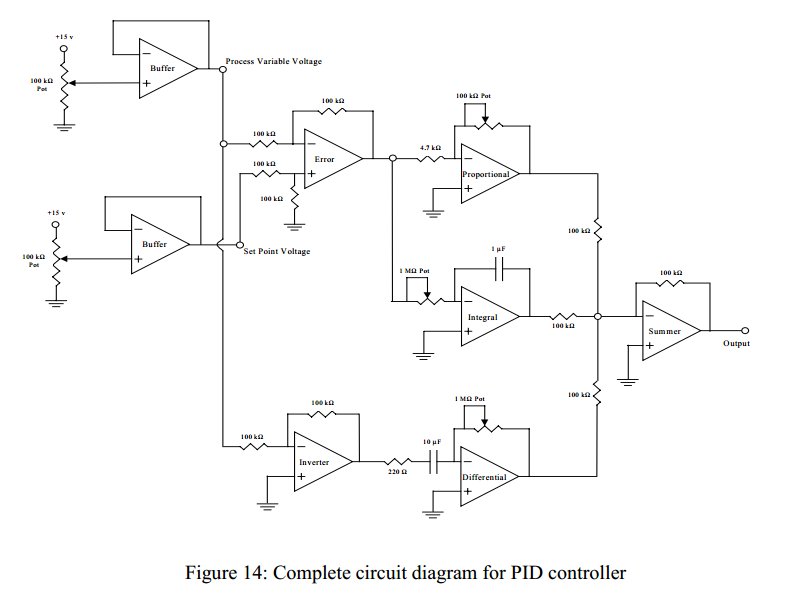
Convert a feedforward operational amplifier PID loop to C code. Assistance is needed for this conversion, as the process is unfamiliar. Input values can be obtained through an ADC, such as voltage or current, but coding a feedforward PID...

A telephone utilizes electric current to transmit sound information between homes. During a conversation, a steady electric current flows through both telephones, which share this current. As one person speaks into their telephone's microphone, the current drawn from the...

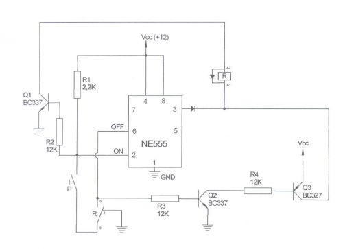
The 555 timer is configured as a multivibrator in conjunction with an opto-isolator to drive a remote speaker. The circuit utilizes the 555 timer in astable mode to generate a continuous square wave output. This output is then used to...
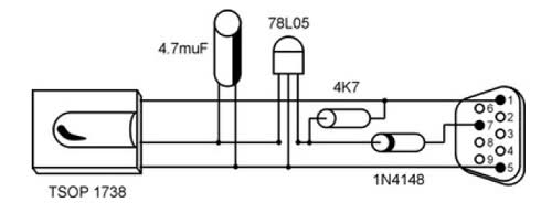
It is unusual that personal computers are not equipped with a standard remote control interface. Many motherboards feature an IRDA port; however, this port is not compatible with the 38 kHz frequencies commonly used by regular remote controls. Fortunately,...
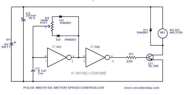
A simple PWM motor speed control circuit with a diagram and schematic for low power DC motors. This easy-to-make PWM DC motor controller is created using the IC CD40106B. The PWM (Pulse Width Modulation) motor speed control circuit utilizes the...