
Contactless Tachometer

The tachometer circuit operates on the principle of optical sensing, utilizing an LED and photodiode pair to detect the presence of light interrupted by the rotating wheel's holes. The LED emits light, which is directed toward the photodiode. As the wheel rotates, the holes allow light to reach the photodiode intermittently, generating a series of electrical pulses corresponding to the wheel's revolutions. These pulses are then processed by the op-amp, which amplifies the signal for further processing.
The choice of the photodiode over a phototransistor is significant, as photodiodes generally provide faster response times and better linearity, making them suitable for applications requiring precise measurements of rotation speed. The operational amplifier plays a critical role in transforming the photodiode's current output into a usable voltage signal, which is essential for accurate RPM calculations.
The TTL level converter ensures compatibility between the sensor output and the Arduino input, allowing for seamless integration of the tachometer with the microcontroller. The Arduino processes the frequency of the received pulses to calculate the RPM, which is displayed on the LCD. The use of a 16x2 LCD facilitates easy reading of the RPM value, enhancing user interaction with the device.
In summary, this tachometer project exemplifies a practical application of electronic components, demonstrating how simple light-sensing technologies can be employed to measure rotational speed accurately. The design is adaptable, allowing for modifications such as varying the number of holes in the wheel to improve resolution or changing the display method based on user preference.The techometer also called revolution counter is an instrument that measure the speed of a rotating machinery. Generally these measurements are rated in revolutions per minute (R. P. M). In this project we have decided to make our own sensor using a led as light source and a photo diode to pick up the pulse.
A arrangement has to be made to make a sm all hole about 5mm near to the outer surface of the wheel. Led or any light source is fixed to the one side of the rotating wheel and photo diode to the other side of the wheel. Light will fall on the photo diode when the hole on the rotating wheel comes in line with the photo diode and light source or led.
This way a pulse is picked up every revolution. Resolution can be increased by increasing number of holes in one cycle. Above is the circuit diagram of sensor circuit. In our actual sensor circuit we used a photo diode instead of photo transistor as photo diode was much easily available in market. It is basically a type of proximity sensor which gives a HIGH output when there is no obstacle between LED and photo diode and gives a LOW when there is an obstacle.
Now whenever Infrared rays fall on photo transistor or photo diode free electrons and holes are produced. This leads to increase in current and thereby reducing the voltage at pin number 2 of op-amp (operational amplifiers).
When no infrared rays are incident on photo transistor or photo diode current reduces thereby increasing the voltage at pin number 2 of op-amp. The expression for voltage at pin 2 is: Vcc * { Rsensor / (Rsensor+R1) } Rsensor is resistance of sensor, which is low when light false on it otherwise it is high.
The value of R1 should be carefully chosen to obtain considerable voltage swing in output voltage. We also use a TTL level convertor which converts the output voltage of 3. 8 volts of LM324N to 5 volts and any voltage below 0. 7 volts to 0 volt. We use IC LM3111 for that purpose. We will be attaching a wheel with slots cut out at 30 degree to the shaft of motor whose rpm is to be measured. Whenever a slit passes we get a high pulse at output. We will know how much the wheel has rotated from frequency of output wave. The output is fed to arduino. We will show the output R. P. M. of the motor on a LCD as they are not much difficult to use and are handy. We will use an 16*2 character LCD which contains two rows of eight characters each. LCD has 16 pins and the circuit diagram for connecting it to arduino is shown below. We will be using only 4 data bus lines and use the inbuilt liquidcrystal library for coding purpose. Image of a sample program uploaded in LCD is shown below: We used arduino duemilanove board which contained ATmega328 microcontroller.
We programmed using arduino environment. It consisted of inbuilt liquidcrystal library which we used for interfacing our LCD. The complete arduino code is given here ( Arduino code ). 🔗 External reference
Related Circuits
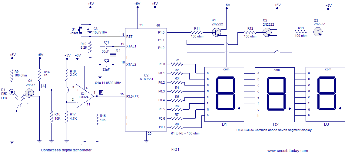
A three-digit contactless digital tachometer utilizing an 8051 microcontroller is presented for measuring the revolutions per second of rotating objects such as wheels, discs, or shafts. The tachometer can measure up to a maximum of 255 revolutions per second...
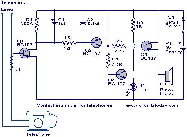
The contactless telephone ringer circuit is designed to produce an audible ring and a visual indication when a call is received. Its primary advantage lies in the absence of direct contact between the telephone line and the circuit, which...
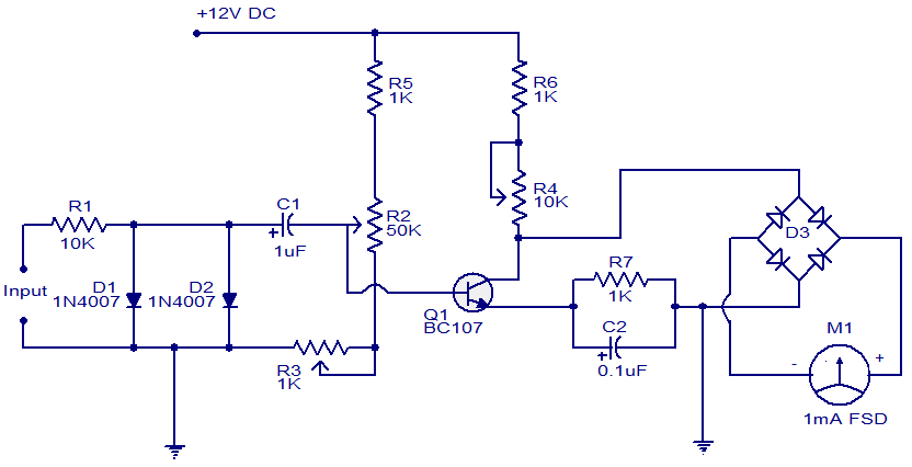
This is a simple circuit that functions as a tachometer. It operates as a frequency-to-current converter, transforming the incoming signal into a proportional current to drive the meter. The deflection on the ammeter correlates directly with the frequency of...
Its based on inductive pickup and very easy to install. Have a look at the pic. (remove LED and connect transistor collector to pin4). I hope it will exactly suits to your tachometer. More: I found your PIC project...
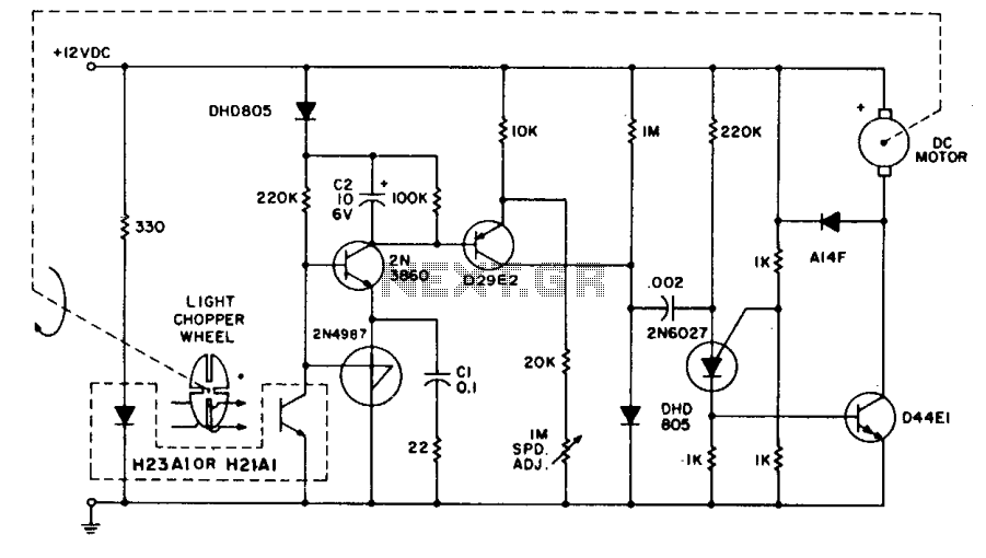
The system employs the H21A1 optocoupler and a chopper disc to achieve enhanced speed regulation. This is effective when the dynamic characteristics of both the motor system and the feedback system are appropriately matched, ensuring stability. The tachometer feedback...
This circuit illustrates the configuration of an ICM7217 and an ICM7555 designed as a basic frequency counter. The connections between the ICM7217 and a common-cathode LED display are depicted in Figure 12-18. Calibration of the frequency counter is accomplished...