
Tachometer circuit

The described tachometer circuit serves as an effective tool for measuring the rotational speed of an engine by interpreting the frequency of the signal generated by the spark plug. The primary components of the circuit include a frequency-to-current converter, an ammeter for displaying the current output, and several resistors for calibration and adjustment purposes.
The operation begins with the connection of terminal A to the spark plug cable, which serves as the signal input. The spark plug generates a high-voltage pulse each time the engine fires, producing a frequency that correlates with the engine's RPM. Terminal B connects to the vehicle's ground to complete the circuit.
Calibration of the circuit is crucial for accurate readings. Initially, resistors R2 and R4 are set to 25K and 5K, respectively. The circuit is powered, and a 60Hz square wave signal is introduced via a function generator. This frequency is chosen as it represents 3600 RPM, a standard reference point for tachometers. Adjusting R2 allows the current output to be set to 0.36 mA, which corresponds to the desired RPM.
After this adjustment, R3 is calibrated to ensure that the meter reads 0 mA when there is no input signal. This step is essential for establishing a baseline reading. If the meter does not reflect the expected 0.36 mA when the 60Hz signal is reintroduced, R4 can be fine-tuned to correct the output.
Safety precautions are paramount due to the high voltage present at the spark plug. The engine must be turned off during the initial setup and calibration to prevent accidental shocks. This circuit design is intended for individuals with a solid understanding of automotive electrical systems, as improper handling can lead to dangerous situations. The circuit's simplicity and effectiveness make it a valuable addition to automotive diagnostics, provided it is used responsibly and with the necessary expertise.Here is a simple circuit that can be used as a tachometer. The circuit is basically a frequency to current converter which converts the incoming signal into a proportional current to drive the meter. The deflection on the ammeter will be proportional to the frequency of the incoming signal. For using this circuit as an automobile tachometer, the i nput terminal A should be connected to the spark plug cable and terminal B should be connected to the vehicles ground. For calibrating the circuit, set R2 at 25K and R4 at 5K. Power up the circuit and feed the input terminal with a 60Hz square wave form your function generator.
Adjust R2 so that the meter shows 0. 36 mA (equal to 3600rpm). Now disconnect the input signal and adjust R3 so that the meter shows 0mA. Now connect the 60Hz signal again and if the meter does not show 0. 36mA adjust R4. A completely calibrated circuit will show 0mA at 0Hz and 0. 36mA at 60Hz. The ignition voltage from the spark plug terminal is in the Kilo volt rage. The engine must be OFF while making connections and you must be very careful to avoid shock hazards. Try this circuit on your automobile only if you have sufficient knowledge and experience on automobile electricals. I have no responsibility on any mishap. 🔗 External reference
Related Circuits
This circuit allows for the control of any line-powered electrical device, such as a lamp, television, or fan, using any infrared remote control. Many individuals possess a collection of old IR remotes from appliances that are no longer in...

This modem/fax protector can be utilized in telephone-line connections between a PC or a terminal and a remote computer. In this circuit, the surge voltage protectors (SVPs) are rated at 230 V. Additionally, a proper grounding is essential for...
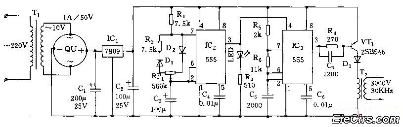
Adjust the RP1 to modify the pulse duty cycle of IC2, which in turn alters the pulse oscillation time of IC3. This regulation allows for the control of ozone generation time, effectively changing the concentration of ozone in the...
It is possible to easily generate various non-linear functions such as X^(1/2), X^2, X^3, 1/X, XY, and X/Y using logarithms. In this context, division is transformed into subtraction, while multiplication is converted into addition. The application of logarithmic properties in...

This is a circuit design for a digital voltmeter with an LED display. It is suitable for measuring the output voltage of a DC power supply. The circuit features a 3.5-digit LED display with a negative voltage indicator and...
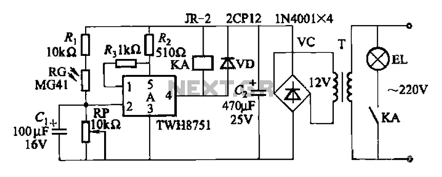
The adjustment potentiometer RP can modify the sensitivity of the device. Capacitors C1 function as an anti-light interference mechanism for instantaneous action. The adjustment potentiometer (RP) is a variable resistor that allows for fine-tuning of the device's sensitivity. By altering...