
Continuity Tester For Low-Resistance circuits

The continuity tester is a fundamental tool used in electrical diagnostics to determine whether a circuit is complete or if there are breaks in the path. The basic configuration includes a battery, which serves as the power source, and a lamp that acts as an indicator. When the circuit is complete, current flows through the lamp, causing it to illuminate.
The alligator clip is designed for easy attachment to various points in a circuit, allowing for efficient testing without the need for additional tools. The probe tip is used to make contact with other components or wires, enabling the user to check continuity at different locations.
In a typical setup, the battery voltage is chosen based on the specifications of the lamp to ensure adequate brightness when the circuit is complete. Commonly, a 9V battery is used with a small bulb, such as an LED or a miniature incandescent bulb, to provide a clear visual indication of continuity.
The circuit can be represented schematically with the battery symbol connected in series to the lamp symbol, with lines indicating the connections to the alligator clip and probe tip. The alligator clip and probe tip are usually depicted as separate terminals, allowing for clear identification of the testing points.
In terms of safety and usability, it is essential to ensure that the voltage used is appropriate for the components being tested to prevent damage. Additionally, the design should incorporate a durable casing for the battery and lamp assembly to withstand regular use in various environments.
Overall, the continuity tester is a simple yet effective device, crucial for troubleshooting electrical systems, ensuring that circuits are intact and functioning correctly. The continuity tester is little more than a battery and a lamp connected iri series, with one end of the string terminated in an alligator clip, and the other end connected to the probe tip.
Related Circuits
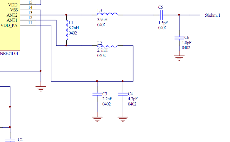
Place the transceiver and the chip antenna very close together, eliminating the need for a 50-ohm transmission line. If this is the case, can the two matching circuits be merged into one to reduce the component count? To create an...
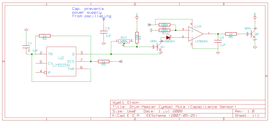
This page contains various small circuits created over time. Some circuits are trivial, while others are more complex, but all are intended to be useful for a variety of projects. Most include both the schematics and the source (KiCad)...
This small circuit is designed to verify the basic functionality of an infrared remote control unit. The circuit utilizes a straightforward approach by connecting a piezo buzzer directly to an IR receiver integrated circuit (IC). This configuration is as...
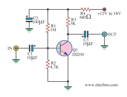
When there is a need to amplify audio signals from various sources before they reach a custom amplifier, a preamplifier (or preamp) is typically employed. This document suggests a specific circuit that is interesting due to its use of...
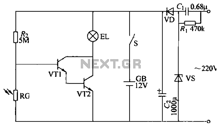
The power supply circuit features a step-down capacitor (C1), bleeder resistors (R), a Zener diode (VS), a full diode (VD), and a filter capacitor (G), along with switches and batteries (GB, SC). The light control circuit is composed of...

A multi-wire cable tester features a separate LED indicator for each wire. It is capable of detecting open circuits, short circuits, reversals, earth faults, and continuity, utilizing four integrated circuits (ICs). Initially designed for intercom systems, it is also...