
control interfacing keypad and lcd

The circuit serves as an educational tool that facilitates the understanding of interfacing techniques between microcontrollers and peripheral devices. The 4x4 matrix keypad allows for the input of multiple signals, which are read by the HCS12 microcontroller. Each key press corresponds to a specific binary output, which the microcontroller processes to perform various functions. The keypad is connected to the microcontroller's GPIO pins, enabling it to detect which key is pressed based on the combination of rows and columns activated.
The LCD display, specifically the DCM-20434 model, is a versatile output device that provides visual feedback to the user. By using the SPI-0 serial port, the microcontroller communicates with the 74HC595 serial to parallel converter, which transforms the serial data stream into parallel data suitable for the LCD. This conversion is crucial as the LCD operates in a parallel mode, allowing for faster data transmission and display updates.
In the configuration process, the four-bit mode of the LCD is essential for reducing the number of data lines used, simplifying the circuit design. By connecting DB3 through DB0 to ground, the circuit effectively utilizes only four data lines for communication, which is adequate for sending commands and data to the LCD. The remaining control lines, such as RS (Register Select) and E (Enable), must be managed correctly to ensure proper operation of the display.
To successfully implement this circuit, it is imperative to follow the guidelines provided in the schematics and documentation for both the SPI serial port and the LCD display specifications. This knowledge will ensure that students can effectively interface these devices, enhancing their understanding of microcontroller applications in practical scenarios.This is circuit for interfacing I/O keypad and LCD that can study in laboratory for student to experience interfacing basic I/O devices to the HCS12 microcontroller mounted on the CML12S-DP256 development board. The keypad that using in this circuit is a standard 4 X 4 matrix keypad with 4 rows and 4 columns. This is the figure of the interfacing of keypad. The DCM-20434 LCD display is interfaced to the MCU`s SPI-0 serial port through a serial to parallel converter as shown in Figure 3. Figure 3 shows the interface connections between the SPI-0 serial port, the 74HC595 (serial to parallel converter) device, and the LCD-PORT.
The DCM-20434 LCD should be configured in four bit mode as the schematic shows DB3 through DB0 connected to ground. This is the interface figure. To interface the LCD display to the HCS12 MCU you must understand how the physical layer interface circuit is constructed (shown in Schematics for Development Board), how to configure and use the SPI serial port (SPI Serial Bus Document), and how to configure and use the LCD display (DMC-20434 LCD Specifications ).
🔗 External reference
Related Circuits
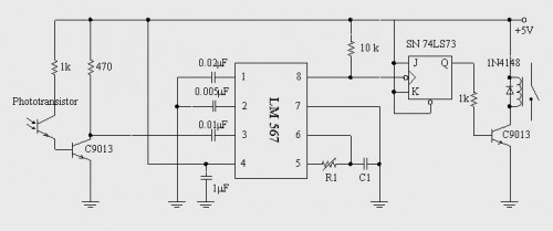
A simple circuit diagram illustrates a schematic for a remote control system, which consists of two parts: the transmitter and the receiver. The transmitter circuit is controlled by an NE555 integrated circuit (IC) and operates by detecting the emitted...
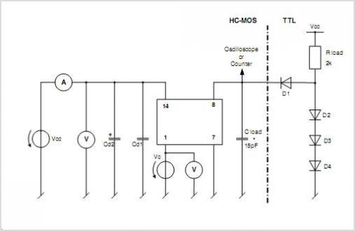
This document does not aim to provide an extensive account of the integrated circuits (ICs) used in this circuit. For additional information on this topic, please refer to the "Flip-Flop Made With A LM556 Timer Chip" section and the...
The OPB350 series liquid sensor is designed to operate with clear tubes of various outer diameters: 1/16 inch (1.6 mm), 1/8 inch (3.2 mm), 3/16 inch (4.8 mm), and 1/4 inch (6.3 mm). When integrated with output reference circuitry,...
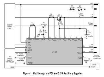
The LTC 4241 is a Hot Swap controller that enables safe insertion and removal of a board from a live PCI-bus slot. It features a primary controller that manages the four PCI supplies, along with an independent auxiliary controller...
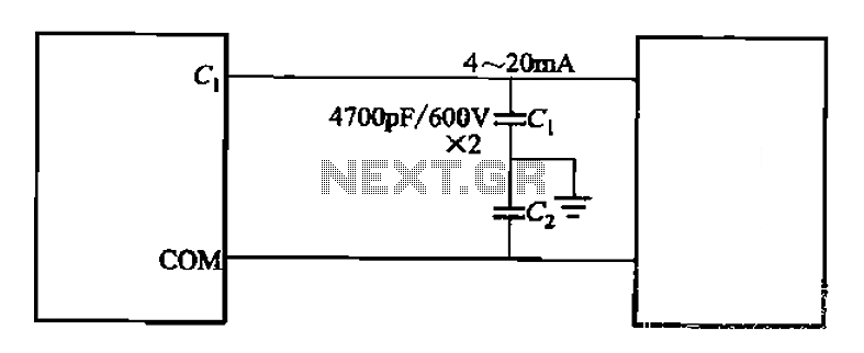
A capacitor filter is utilized in frequency control circuits and is a common method for implementing anti-jamming measures. It addresses frequency interference noise within the wiring of the 4-20mA control loop. The anti-interference is achieved through bypass capacitors C1...
The Olimex P-40 development board will be utilized, though the circuit can also be constructed on a breadboard due to its simplicity. The schematic for the initial implementation of servo control is provided below. Servos, like any motors, can...