
Control cables plus anti-interference capacitors

The capacitor filter circuit serves as an essential component in mitigating electromagnetic interference (EMI) in control systems, particularly those employing 4-20mA analog signals. The use of capacitors C1 and C2 acts as a low-pass filter, effectively shunting high-frequency noise to ground while allowing the desired signal to pass through with minimal attenuation. This filtering action is crucial in environments where external electromagnetic fields can induce unwanted voltage spikes or noise in the signal lines.
In practice, the placement of the capacitors should be as close to the load as possible to minimize the loop area and reduce the potential for inductive coupling of noise. The choice of capacitor values will depend on the specific frequency characteristics of the noise present in the environment, as well as the bandwidth requirements of the control signal.
Twisted-pair cabling is recommended for the control loop to further enhance noise immunity. The twisting of the wires helps to cancel out any induced noise from external sources, as the electromagnetic interference affects both wires equally, thereby reducing its impact on the differential signal. This configuration is particularly effective in industrial settings where heavy machinery may generate significant electrical noise.
Overall, the combination of capacitor filters and twisted-pair wiring provides a robust solution for ensuring signal integrity in control systems, thereby enhancing the reliability and accuracy of the 4-20mA control signals in various applications. Capacitor filter is adopted frequency control circuit commonly used anti-jamming measures. (1) frequency interference clamor of wiring in the cable core wire 4-20mA control plu s anti-interference bypass capacitors Cl and C2, as shown in FIG. Control cables as far as possible with a pair of twisted-pair.
Related Circuits
Here is a circuit for using the printer port of a PC for control application using software and some interface hardware. The interface circuit along with the given software can be used with the printer port of any PC...
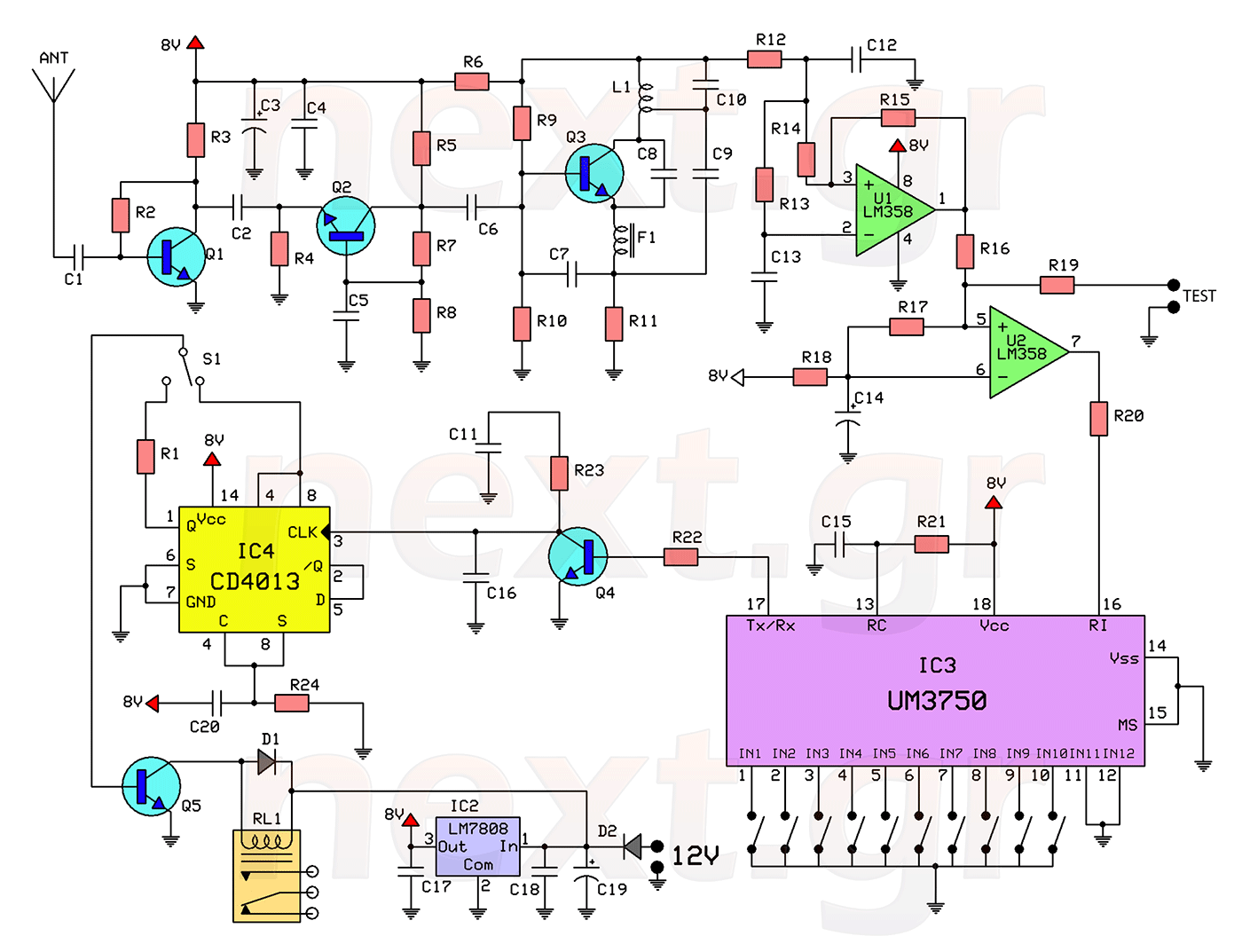
This circuit includes a 2048 radio remote control transmitter and a corresponding wireless receiver that features high reception sensitivity and low power consumption. The combination of these two components provides a highly reliable remote control system, suitable for various...
This page features a circuit that has twenty open collector outputs that turn on one at a time in a continuous sequential manner. The circuit utilizes the 74LSxx family of TTL integrated logic devices. The circuits are designed to...
The initial step often taken when learning about any microcontroller or embedded system is to make an LED blink. The circuit presented below illustrates the setup for interfacing an LED. Note: Due to the large dimensions of the circuit...
A schematic diagram for the remote analyzer is presented. The circuit operates from a basic 5-V power supply, which includes components PL1, S1, T1, a bridge rectifier made up of diodes D1 through D4, capacitor C1, and a common...
A device that provides a USB port is recognized as a "CP2103 USB to UART Bridge Controller" when connected to a Windows PC. According to the device documentation, it communicates in serial format at 38400 bps. The USB pinout...