
Controlling a LED using a switch

The circuit design consists of an Arduino microcontroller, a switch, an LED, and two resistors (10kΩ and 470Ω). The switch is connected to one side of the Arduino digital pin, while the other side is connected to ground through the 10kΩ resistor. This configuration ensures that when the switch is open (not pressed), the digital pin is pulled low to ground, preventing it from floating. The 10kΩ resistor serves to limit the current to the ground, thus protecting the microcontroller from excessive current draw.
When the switch is closed (pressed), the digital pin is connected to the positive voltage supply (5V), allowing current to flow through the 470Ω resistor and the LED. The LED will illuminate as long as the switch is pressed, and the 470Ω resistor serves to limit the current through the LED to a safe level, preventing damage.
The software component requires initializing the digital pins in the Arduino environment. A loop continuously checks the state of the switch. If the switch is detected as pressed, the LED will be activated; if not, the LED will remain off. The use of an infinite loop allows for real-time monitoring of the switch state, ensuring immediate response to user input.
This circuit is a fundamental example of interfacing digital inputs and outputs with an Arduino, showcasing basic principles of electrical engineering, such as current limiting, voltage levels, and digital logic. Proper implementation guarantees efficient operation while safeguarding the components involved.To create the circuit you will need to connect a switch as an input and an LED as an output to the Arduino. This means that you will need a switch, an LED, a 10k © resistor, a 470 © resistor, a blue or yellow jumper wire, and a red jumper wire.
The Arduino pin is connected to the circuit between the resistor and the switch. This is because the digital pin is configured such that it needs a small amount of power to change states. This is useful since we don`t want to draw too much power through the Arduino. However, this also means that if the pin is not connected to a known level in the circuit, it could have any value. This is called floating, since the value of the pin is neither high nor low. To solve this problem we use the resistor to connect the pin to ground. We use a resistor and not just a wire so that we can limit how much current is flowing through the connection.
Since we want to minimize the power draw we will use a large resistor, in this case 10k ©. When the switch is not pressed the pin is only connected to ground through the resistor. Since the pin will have what ever voltage value is applied to it, the resistor can be considered as a wire when the switch is not pressed. However, once the switch is pressed, the pin is directly connected to 5V and the resistor limits the current flowing to just 0.
5 mA, and thus prevents a short circuit. Now that we have everything connected, we need to tell ROBOTC how to configure the pins before we can program. We need to tell ROBOTC that we are using the Parallax BOE Shield, and that we have the LED connected to pin 5.
We also need to tell ROBOTC that pin 2 is a Digital High Impedance (the led switch with the resistor connected to ground) and name it "ledSwitch". We want the Arduino to turn the LED on when the button is pressed and turn it off when it is not pressed.
To do this we will need an infinite while loop and a way to determine the state of the switch. There are a lot of different ways to do this, but for now we will just use a second while loop that only runs when the button is pressed: The "=" means to check if the values to either side are equal. If the values are equal, then it will return true, otherwise it will return false. This is different than the single equals sign "=", which is used when assigning values. So by placing that code inside the second while loop`s condition, we can make that loop only run when the switch is pressed.
🔗 External reference
Related Circuits
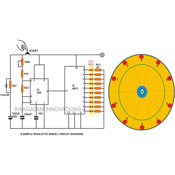
A simple circuit for a 10 LED roulette wheel is presented. Pressing the button initiates the LEDs in a rotational sequence that starts at full speed and gradually decelerates until it halts at a randomly selected LED. The randomness...

The call is made using the ISD1016 language chip for voice generation instead of a traditional phone ringing message controller schematic circuit. This controller can store messages, music, songs, or other sounds, serving as an alternative to monotonous ringing. The...
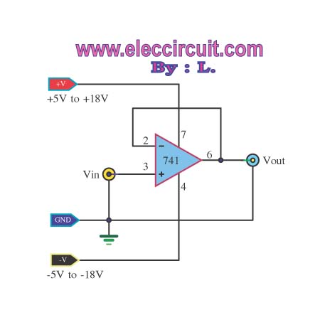
The buffer operational amplifier (op-amp) circuit is utilized for coupling two circuits together. It functions as a unity gain follower, also known as a voltage follower, which is employed to transfer or replicate a voltage from one circuit to...
A 6-watt audio amplifier circuit utilizing the TDA2613 integrated circuit is presented. The TDA2613, produced by Philips Semiconductors, is a high-fidelity audio amplifier IC. This component is designed to be click-proof when switched on or off, resistant to short...

The circuit is designed to deliver approximately 10% distortion on a 4 Ohm to 8 Ohm loudspeaker. The LM4756 amplifier can output 7W of power. Utilizing four pairs of 2SC5200 and 2SA1943 transistors, this configuration can generate around 500W....
Audiostrobe glasses are utilized alongside light and sound machines, as well as certain brainwave entrainment software. The glasses are equipped with built-in LEDs. Audiostrobe glasses are designed to enhance the sensory experience provided by light and sound machines, which are...