
converter lhc20 5ka 18v

The power converter system is integral to the efficient operation of superconducting magnets within the LHC. Its modular architecture allows for scalability and redundancy, ensuring continuous operation even in the event of component failure. The water-cooling system is particularly advantageous in the confined underground environment, where excessive heat generation could lead to operational inefficiencies. The high-frequency operation of the Power Bricks enables rapid response times, which are critical for maintaining stable current levels in superconducting loads.
The integration of advanced monitoring systems, such as the FWD monitoring card, enhances the reliability of the power converter by providing real-time diagnostics. This capability allows for proactive maintenance, minimizing downtime and ensuring the safety of the superconducting magnets. Furthermore, the use of a digital controller with high-precision ADCs ensures that the current control loop operates within strict tolerances, which is essential for the performance of superconducting magnets.
In summary, the design and functionality of the power converter are tailored to meet the demanding requirements of the LHC's superconducting magnet systems, combining modularity, advanced monitoring, and robust safety features to ensure optimal performance in a challenging underground environment.It is located in the LHC underground installation, close to the loads to limit cable losses in the underground installation. A high current switch mode power converter, designed for powering of superconducting loads requiring only positive current and positive voltage control (1 quadrant).
The converter is constructed from a modular architecture composed of 3. 25kA power modules. The converter is water cooled, and is thus ideally suited to situations where air losses must be carefully managed. Designed for underground operation, extensive remote diagnostics have been foreseen to allow efficient monitoring and fault diagnostics without requiring being present locally.
Power Converter is normally assembled using a n+1 Power Bricks [+3. 25kA +18V] to provide active redundancy in case of one subconverter is lost. [+20. 5kA +18V] Power Converter is composed of 8x [+3. 25kA +18V] Power Brick, working as current source being controlled by a Voltage Source main control. Power Brick is actually a high frequency current source (7-8kHz) controlled by a 1kHz bandwidth voltage loop. One can notice that Power Brick is actually a current cource in its structure, even if voltage source capacitors are located in this block for mechanical reasons.
Representation below gives a symbolic structure of the power converter, clarifying the cascade loops. High precision current control loop is managed by the digital controller called FGC (Function Generator Controller).
This unit includes a high precision Sigma Delta Analog to Digital Converter which digitalize the analog current measurement coming from 2 DCCTs (DC current Transducer). Precision is then directly relying on sensor precision: DCCT, the ADCs, and the algorithm being used for the regulation loop.
Voltage source is then used as a power amplifier, powering the load through a high bandwidth voltage loop (>500Hz). Power Converter is part of magnet protection scheme, even if not directly fully responsible of the monitoring and diagnostic of the superconductive magnet status.
Dedicated systems QPS (Quench Protection System) + PIC (Power Interlock Controller) can interlock Power Converter if magnet safety requires it. Always ensure that external protection system can stop the Power Converter through a safe signal called Fast Abort.
This redundant signal uses 2 paths to interlock and stop the converter and its redundancy is checked each time it acts. Each free wheel diode module is electronically monitored for open-circuit and short-circuit by a Free Wheeling Diode Monitoring Card.
The monitoring principle is as follows: The current inside each diode module is measured through a FWD monitoring card using voltage taps over each diode module`s connection cable (which works as a shunt): maximum 16 channels per FWD monitoring card. Each individual diode module current is compared to the average. If the difference exceeds a preset threshold, then the corresponding diode is considered faulty and signalled by a red Led on the FWD monitoring card.
A global FWD fault alarm is also generated by the card. When several FWD monitoring cards are used, the global alarm of each FWD monitoring card is connected in a daisy chain generating one FWD fault at the level of the Common Control Electronics for remote diagnostic. A power converter is actually a sum of different equipments under several different sections in the TE-EPC group.
The modularity is a key factor for easier maintenance with regards to LHC tunnel access conditions. 🔗 External reference
Related Circuits
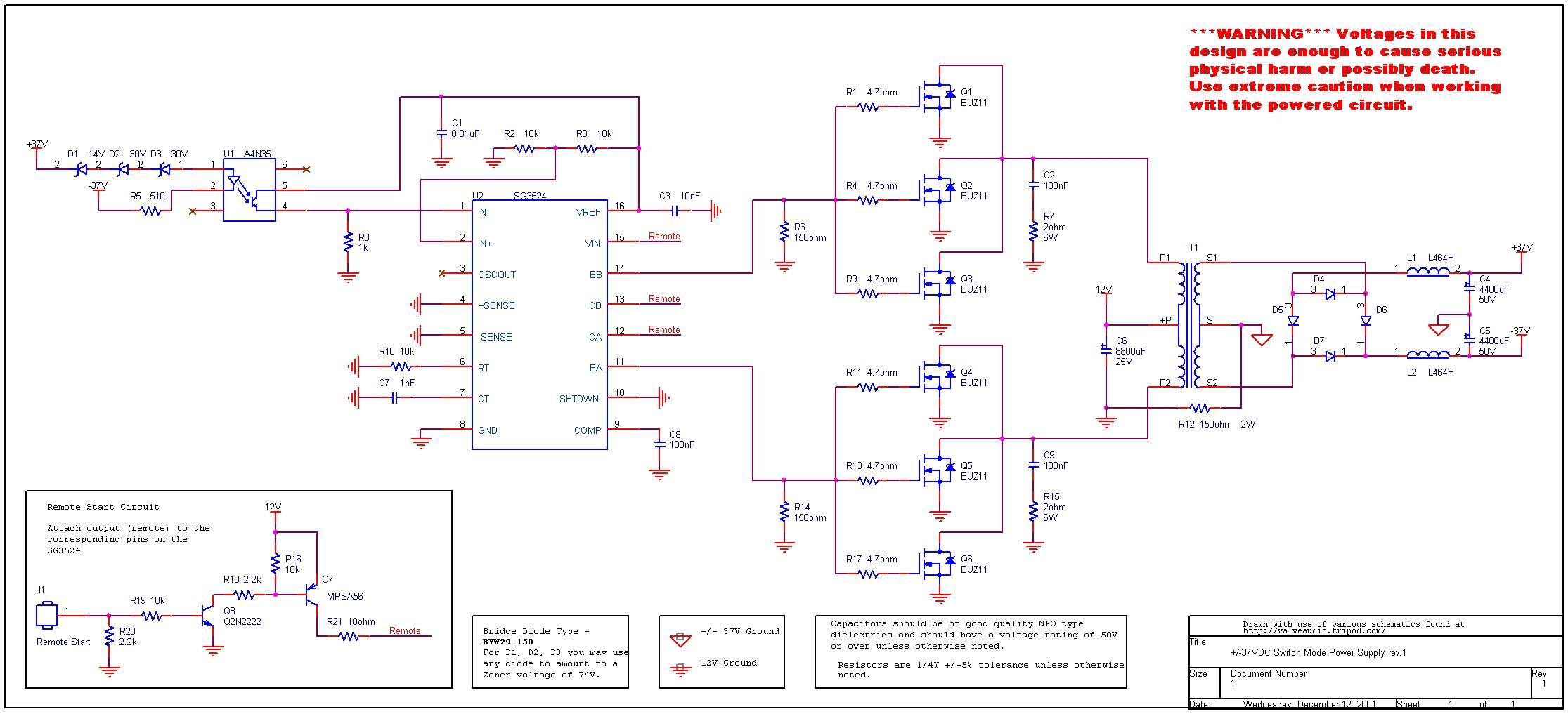
12VDC to 37V DC converter using SG3524. The circuit described is a DC to DC converter designed to convert an input voltage of 12V DC to an output voltage ranging from 0V to 37V DC. This circuit utilizes the SG3524...
This inverter circuit can provide up to 800mA of 12V power from a 6V supply. For example, you could run 12V car accessories in a 6V (British?) car. The circuit is simple, about 75% efficient and quite useful. By...
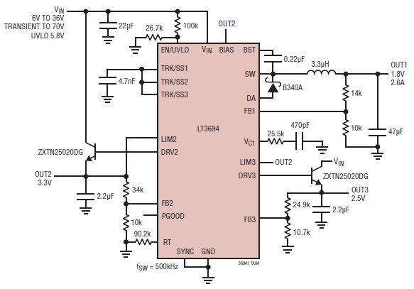
The LT3694 is a monolithic, current mode DC-DC converter that can be designed as a simple step-down converter, supporting a maximum output current of 2.6 A. This switching step-down converter is capable of generating up to 2.6 A at...
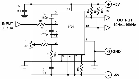
A voltage-to-frequency converter with a control range of 1:1000 can be constructed using the IC TSC9402. The specified component values in the circuit yield a conversion factor of 1 kHz per 1 V. Input voltages ranging from 10 mV...
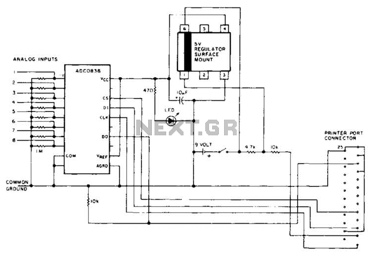
An A/D converter by National Semiconductor (ADC0838) converts 0 to 5 V analog inputs into a digital data format. A 9 V battery is utilized. The converter connects to the pointer port connector through a 25-pin connector. The ADC0838 is...
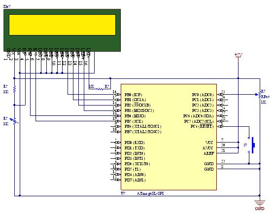
A straightforward tutorial on utilizing the ADC (Analog to Digital Converter) unit of the AVR microcontroller, demonstrated with the Atmega8, including a circuit diagram and code examples. The ADC unit in the Atmega8 microcontroller is a crucial component that allows...