
Cookers circuit

The modern cooker circuit typically involves a combination of heating elements, control systems, and safety features designed to enhance user convenience and energy efficiency. The circuit is generally powered by an AC supply, which is transformed and rectified to provide the necessary voltage and current levels suitable for the heating elements.
At the core of the cooker circuit is the heating element, often made of materials such as nichrome, which has a high resistance and can generate heat when an electric current passes through it. This element is connected in series with a temperature control unit, which can include a thermostat or a digital temperature sensor. The control unit regulates the power supplied to the heating element based on the desired cooking temperature, ensuring efficient energy use and preventing overheating.
In addition to the heating element and control system, safety features such as fuses or circuit breakers are integrated into the cooker circuit. These components protect against overcurrent conditions that could lead to electrical fires or damage to the appliance. Furthermore, many modern cookers are equipped with user interfaces, such as LED displays or touch panels, that allow consumers to easily select cooking modes, set timers, and monitor cooking progress.
The cooker circuit may also include additional functionalities, such as automatic shut-off features, which enhance safety by turning off the heating element after a specified period or when the cooking process is complete. This not only prevents accidents but also conserves energy.
Overall, the design of the cooker circuit prioritizes efficiency, safety, and user-friendliness, making it an essential component in modern cooking appliances.Currently using cookers become a fashion, because fast, clean, pollution, etc., by consumers favorite. Cookers circuit
Related Circuits
This is a basic 555 square wave oscillator used to produce a 1 kHz tone from an 8-ohm speaker. In the circuit on the left, the speaker is isolated from the oscillator by an NPN medium power transistor, which...
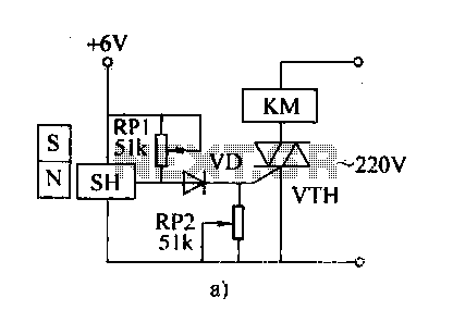
The automatic weapon features a magnetic switch circuit that is simple, reliable, has a low failure rate, and offers good versatility. It can be used for output performance or converted into mechanical displacement applications. The circuit diagram utilizes a...
The photocell photoelectric tracking circuit is configured with two identical photoelectric cells that serve as light-receiving devices. When the incident light intensity is equal, the system is able to track in a predetermined manner. If there is a slight...
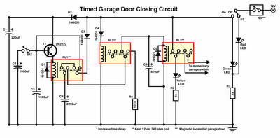
Timer garage door circuit schematic diagram, printed circuit board. The timer garage door circuit is designed to automate the opening and closing of a garage door based on a predetermined time interval. The schematic diagram illustrates the layout and connections...
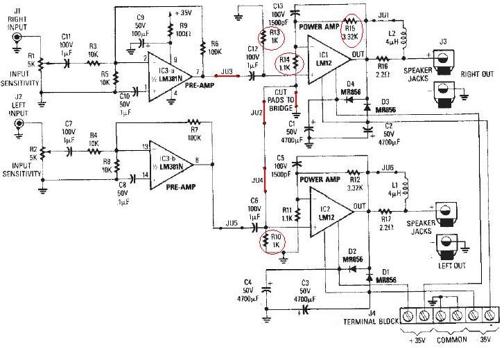
The LM12 audio amplifier circuit is designed to deliver high output power for loads with impedances of 4 ohms or 8 ohms. The maximum output power achievable by this amplifier is approximately 60 watts for a 4-ohm load and...

R1 is a 15k ohm resistor. An NTC thermistor rated at 10k ohm, available at Radio Shack in the United States, is utilized. P1 is a 10k ohm potentiometer that sets the low speed (voltage) of the fans at...