
lm12 audio amplifier circuit diagram

The LM12 audio amplifier circuit is composed of several key components that work together to achieve high fidelity audio amplification. The LM381N serves as the preamplifier, providing initial signal amplification and ensuring that the audio signal is at an adequate level before it reaches the power amplifier stage. This dual preamplifier IC is capable of handling low-level audio signals, effectively minimizing noise and distortion.
The power amplifier stage, based on the LM12 operational amplifier, is responsible for delivering the final amplified audio signal to the speakers. The LM12 is renowned for its ability to handle high output currents, making it suitable for driving loads such as 4-ohm and 8-ohm speakers. With a maximum output power of 60 watts at 4 ohms and 100 watts at 8 ohms, this amplifier can efficiently drive a range of audio applications, from home audio systems to public address systems.
When configuring the amplifier in bridge mode, it is important to note that the circuit will operate as a mono amplifier. This configuration effectively doubles the output voltage, allowing for greater power delivery to a single load. To switch between bridge mode and stereo mode, the PCB design must accommodate the necessary modifications. This includes routing the audio signals appropriately and adjusting jumper settings to ensure that the amplifier operates correctly in the desired configuration.
The PCB layout should be designed with careful consideration of component placement to minimize interference and maintain signal integrity. Adequate heat dissipation measures must also be implemented, particularly for the LM12, as it can generate significant heat during operation. This may involve the use of heat sinks or other cooling methods to ensure reliable performance.
Overall, the LM12 audio amplifier circuit is a versatile solution for high-power audio amplification, with the flexibility to be configured for various applications based on user requirements. Proper design and implementation of the circuit will ensure optimal performance and audio quality.This LM12 audio amplifier circuit will provide a high output power on a 8 ohms or 4 ohms load impedance. The maximum output power delivered by this LM12 audio amplifier is around 60 watts on a 4 ohms load and 100 watts on a 4 ohms load on each channel.
A preamplifier stage based on the LM381N dual preamplifier integrated circuit and a power ampl ifier stage based on the LM12 high power operational amplifier. To obtain more audio power from this audio amplifier you can use it in the bridge mode configuration, but in that way you will obtain a mono power amplifier circuit. If you want to use it in bridge configuration or stereo configuration just design the pcb board in the stereo mode configuration and modify the jumpers in this way :
🔗 External reference
Related Circuits
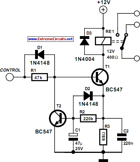
Some relays will become warm if they remain energized for some time. The circuit shown here will actuate the relay as before but then reduce the hold current through the relay coil by about 50%, thus considerably reducing the...
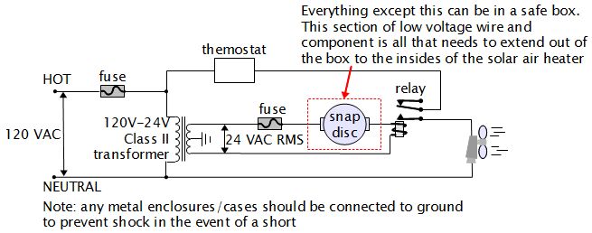
For various experiments, such as solar air heaters, an automatic fan activation and deactivation system is required. A straightforward solution is to use a bimetal snap disc thermal sensor. This sensor functions as a switch that closes when a...
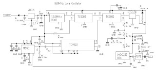
This 860 MHz Phase Locked Loop (PLL) oscillator circuit is designed for a 1200 MHz transverter's local oscillator with 435 MHz rigs. The oscillator utilizes Toshiba PLL synthesizer integrated circuits (ICs). The TC9122P serves as a preset counter for...
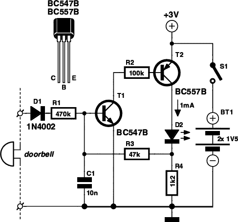
If you are expecting an important visitor but need to step out for a moment, an electronic doorbell memory can be useful to check whether someone rang while you were away. While it cannot confirm if it was the...
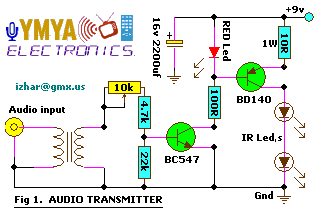
This project allows for wireless transmission of audio from a television to headphones using infrared (IR) technology. It eliminates the need for physical connections between the TV and the headphones. Instead of traditional wiring, it employs infrared light to...
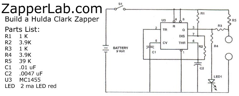
Modify a zapper circuit (similar to the Hulda Clark Zapper) to produce two different frequencies. One switch should be used to set the pulse to 15Hz, and another switch to set it to 30Hz. The nominal frequency for this...